Introduction
The heat sink helps keep the processor cool and happy.
Tools
Parts
-
-
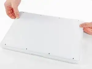
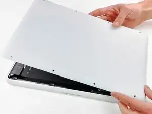
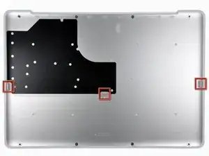
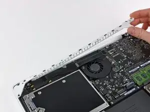
Slightly lift the lower case near the vent opening.
-
Continue running your fingers between the lower and upper cases until the upper case pops off its retaining clips.
-
-
-
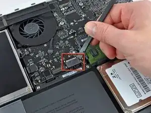
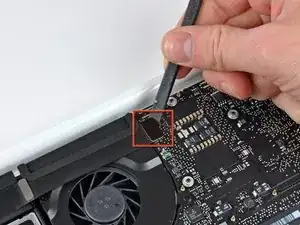
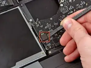
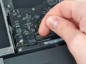
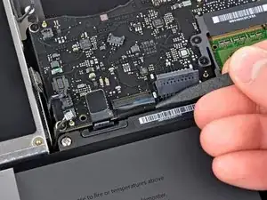
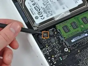
Use the flat end of a spudger to lift the battery connector up out of its socket on the logic board.
-
-
-
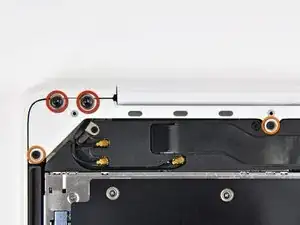
Remove the following screws from the optical drive side of the rear vent:
-
Two 10 mm T8 Torx
-
Two 5.2 mm Phillips
-
-
-
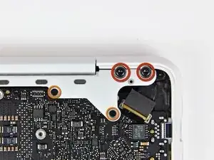
Remove the following screws from the port side of rear vent:
-
Two 10 mm T8 Torx
-
Two 5.2 mm Phillips
-
-
-
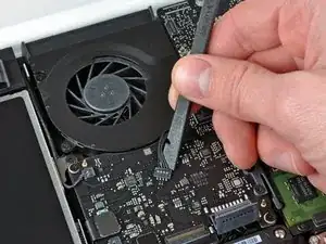
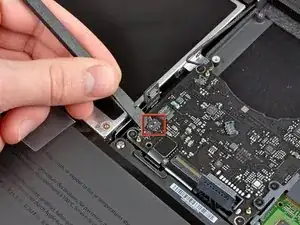
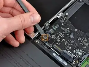
Use the flat end of a spudger to pry the AirPort/Bluetooth ribbon cable up off the logic board.
-
-
-
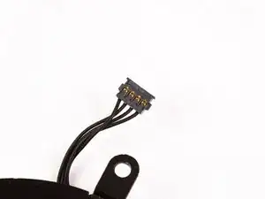
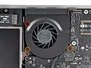
Remove the following three screws securing the fan to the upper case:
-
One 7.1 mm Phillips screw.
-
Two 5 mm Phillips screws.
-
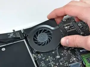
Lift the fan out of the upper case.
-
-
-
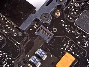
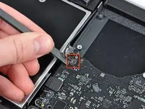
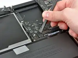
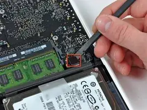
Carefully pry the delicate rear speaker connector up off the logic board. These small L/R speaker connectors are quite easily broken.
-
-
-
Use a spudger to pry the right speaker connector and sleep LED connector up off the logic board.
-
-
-
Use the flat end of a spudger to pry the trackpad ribbon cable connector up off the logic board.
-
-
-
Use your fingernail to flip up the locking flap on the ZIF socket for the keyboard ribbon cable.
-
Use the tip of a spudger to slide the keyboard ribbon cable out of its socket.
-
-
-
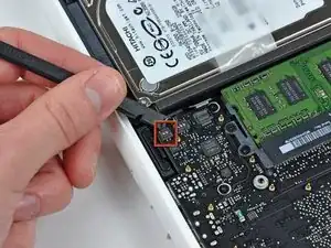
Use a spudger to pry the left speaker connector and microphone connector up off the logic board.
-
-
-
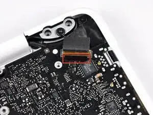
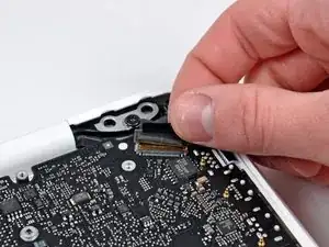
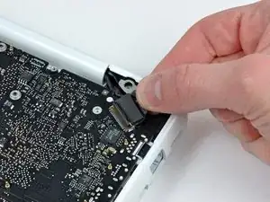
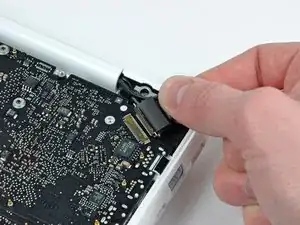
Grab the plastic pull tab secured to the display data cable lock and rotate it toward the DC-In side of the computer.
-
-
-
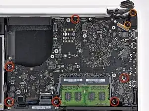
Remove the six 4.1 to 4.4 mm T6 Torx screws securing the logic board to the upper case.
-
Remove the two 4.1 to 4.5 mm T6 Torx screws securing the MagSafe board to the upper case.
-
On some models, these screws may be T7. Be careful not to strip away the head with a smaller bit.
-
-
-
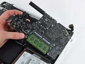
Lift the side of the logic board opposite the ports out of the upper case.
-
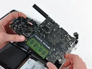
Rotate the logic board away from the upper case until the ports clear the lip molded in the upper case.
-
Pull the logic board and MagSafe board away from the edge of the upper case as one piece.
-
-
-
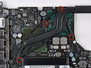
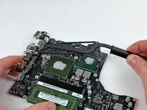
Remove the four 8.3 mm shouldered Phillips screws securing the heat sink to the logic board.
-
To reassemble your device, follow these instructions in reverse order.
7 comments
I really need to replace the thermal paste but, man, this is A LOT of screws!!!
yeah same bro. im going to upgrade the ram, replace the drive with another hard drive, and re paste it.
Thanks for the guide guys, much appreciated. When I order the new screen I’ll update this comment if there was anything interesting about my heatsink repasting.
It works, thank so much guys.
p.mikes -
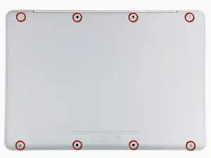

According to this page http://support.apple.com/kb/HT1651?viewl..., the 8 screws are not identical.
Can anybody tell me where each kind of screw is supposed to go?
Gregoire -
They are all 100% Identical. You were probably looking at a different model, or Apple has entered the wrong information... Hey, It happens...
Owen Davies -