Introduction
Use this guide to replace one or both speakers in your MacBook Pro 16" late 2023 (M3 Pro/M3 Max).
Replacing the speakers requires you to remove the logic board and fans. Removing the battery is optional but recommended to prevent bending or puncturing the battery cells adjacent to the speakers.
You'll need replacement speaker and battery adhesives to complete this repair.
Some photos in this guide are of the previous model MacBook Pro and may contain slight visual discrepancies, but they won't affect the procedure.
-
-
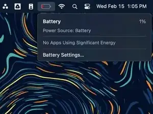
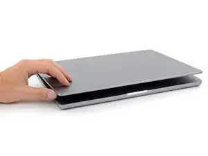
Fully shut down your MacBook, close the lid, and flip it over. Keep the lid closed until you've physically disconnected the battery.
-
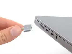
Unplug the MagSafe cable and any accessories connected to your MacBook.
-
-
-
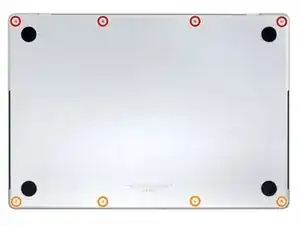
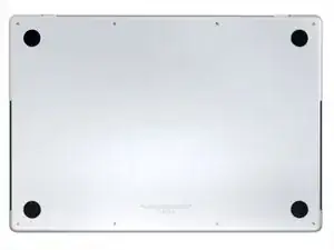
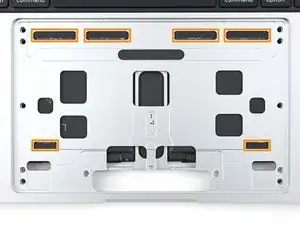
Use a P5 Pentalobe driver to remove eight screws securing the lower case:
-
Four 9.2 mm screws
-
Four 5 mm screws
-
-
-
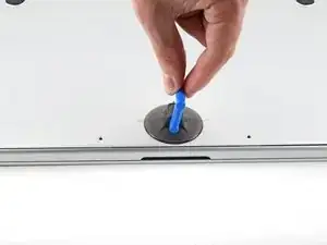
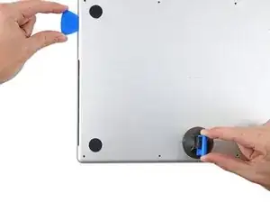
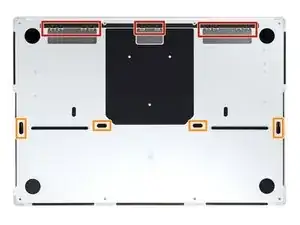
Press a suction handle into place near the front edge of the lower case, between the screw holes.
-
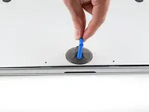
Pull up on the suction handle to create a small gap under the lower case.
-
-
-
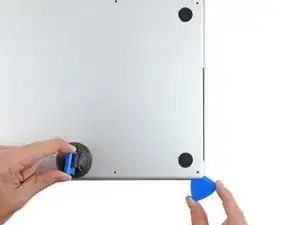
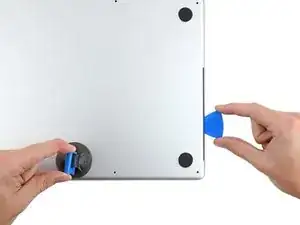
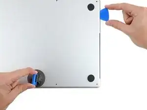
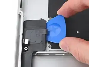
Insert an opening pick into the gap you just created.
-
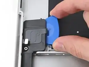
Slide the opening pick around the nearest corner and then halfway up the side of the MacBook Pro.
-
-
-
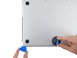
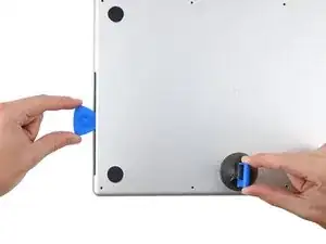
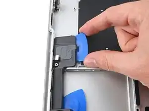
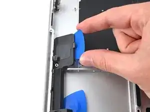
Repeat the previous step on the other side, using an opening pick to to release the second clip.
-
-
-
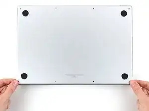
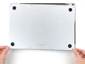
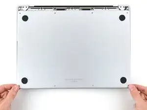
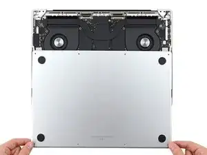
Firmly pull the lower case away from the back edge, one corner at a time, to disengage the sliding clips.
-
-
-
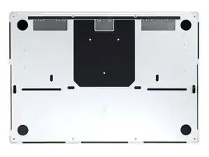
Remove the lower case.
-
Set it in place and align the sliding clips near the screen hinge. Press down and slide the cover toward the hinge. It should stop sliding as the clips engage.
-
When the sliding clips are fully engaged and the lower case looks correctly aligned, press down firmly on the lower case to engage the four hidden clips underneath. You should feel and hear them snap into place.
-
-
-
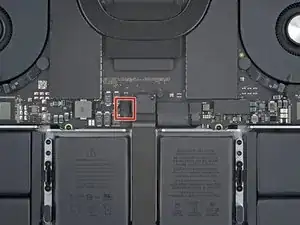
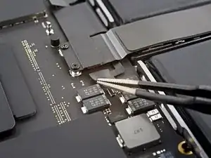
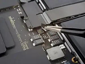
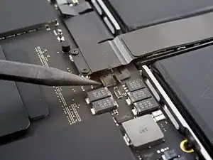
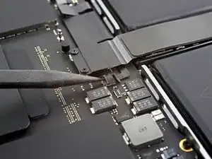
Use a spudger to gently pry up the locking flap on the ZIF connector for the battery board data cable.
-
-
-
Disconnect the battery board data cable by sliding it out from its socket on the logic board.
-
-
-
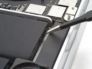
Use a T3 Torx driver to remove the two 2.1 mm‑long screws securing the trackpad cable bracket to the logic board.
-
-
-
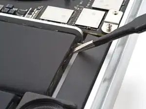
Use the flat end of a spudger to pry up and disconnect the trackpad cable's press connector from the logic board.
-
-
-
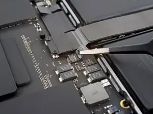
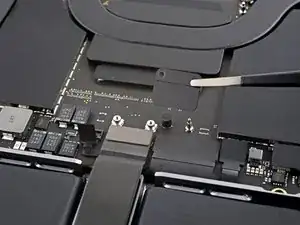
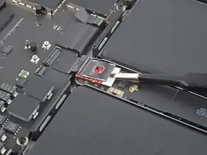
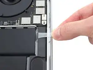
Peel back any tape covering the battery board data cable connector under the large pancake screw.
-
-
-
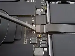
Use a spudger to gently pry up the locking flap on the ZIF connector for the battery board data cable.
-
-
-
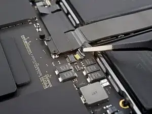
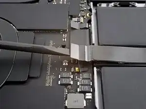
Disconnect the battery board data cable by sliding it out from its socket on the battery board.
-
-
-
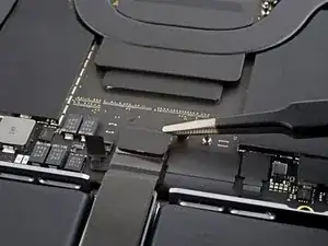
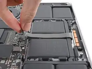
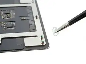
Slide blunt nose tweezers under areas with adhesive to separate the cable from the device.
-
Remove the battery board data cable.
-
-
-
Use the flat end of your spudger to lift the battery connector away from the battery board, disconnecting the battery.
-
-
-
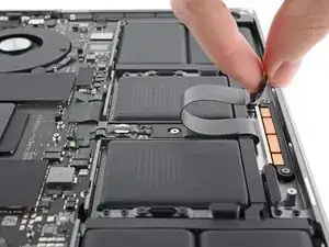
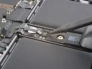
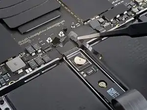
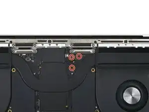
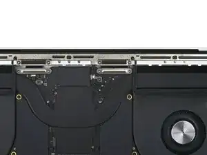
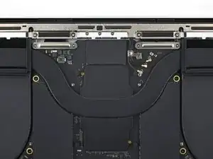
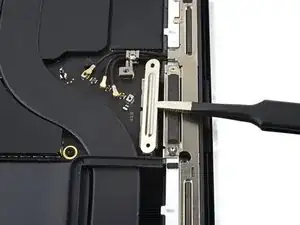
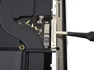
Use a T3 Torx screwdriver to remove the three 2.1 mm screws securing the antenna bar bracket and coaxial cable cover to the frame.
-
-
-
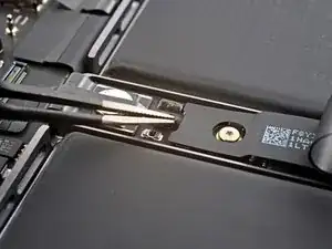
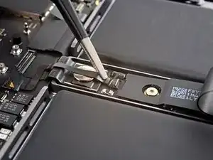
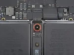
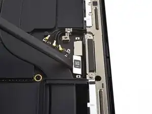
Use tweezers, or your fingers, to remove the cover on top of the antenna bar's coaxial cables.
-
-
-
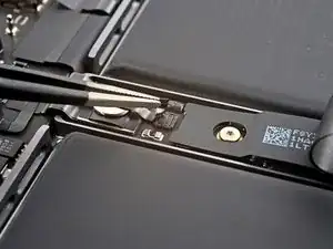
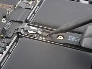
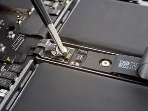
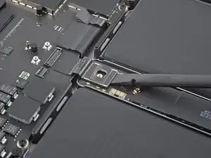
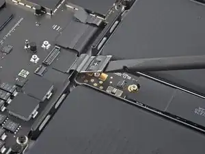
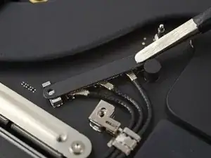
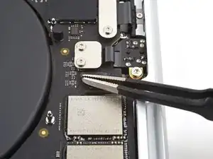
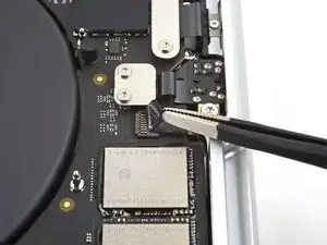
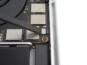
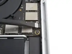
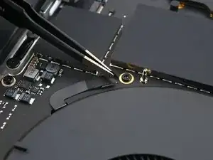
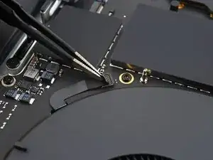
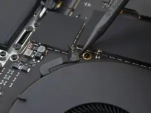
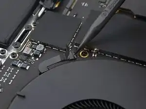
Use the tip of a spudger to pry up and disconnect the antenna bar's coaxial cable.
-
Repeat for the two other cables.
-
-
-
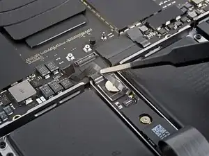
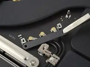
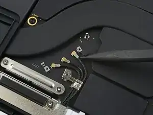
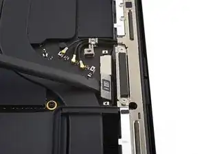
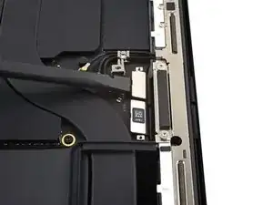
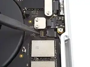
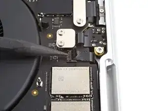
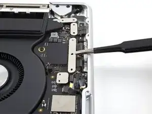
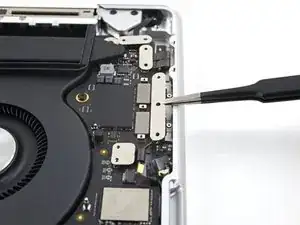
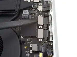
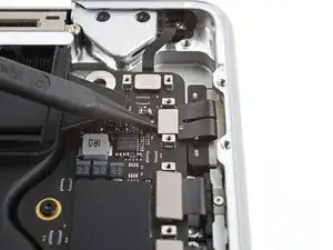
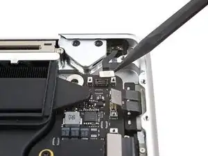
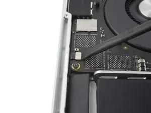
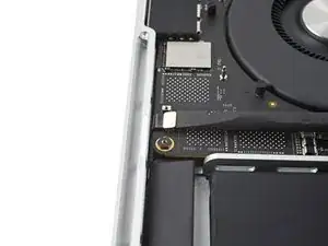
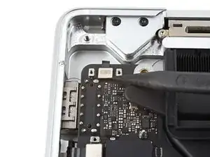
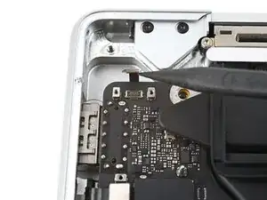
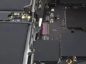
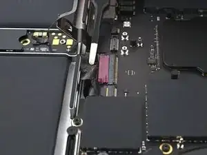
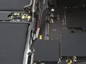
Use the flat end of a spudger to pry up and disconnect the two right-most screen cable press connectors secured to the logic board.
-
-
-
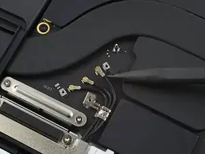
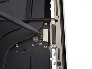
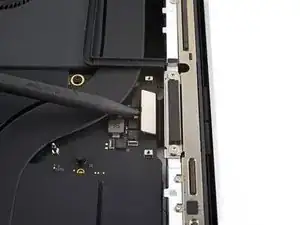
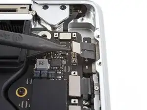
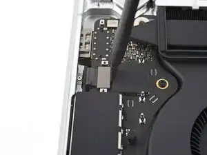
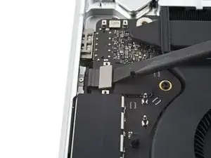
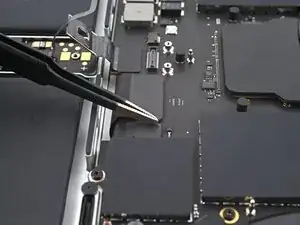
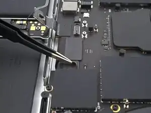
Repeat the previous disconnection process for the remaining press connector at the top left of the logic board.
-
-
-
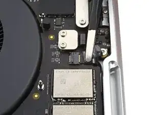
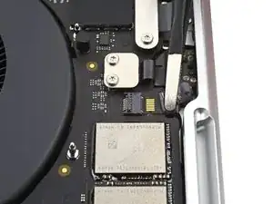
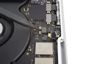
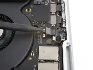
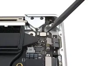
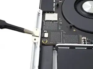
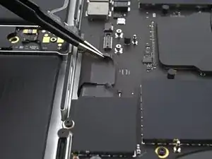
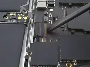
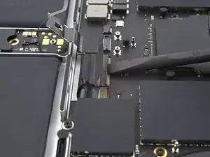
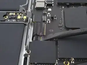
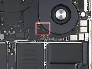
Use a spudger to gently pry up the locking flap on the ZIF connector for the microphone cable.
-
-
-
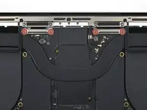
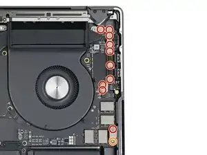
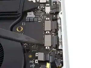
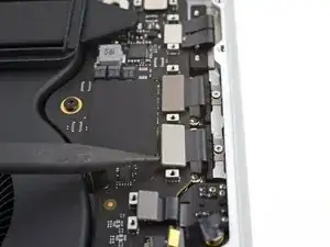
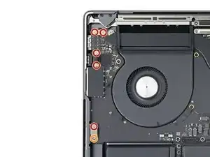
Use a T3 Torx driver to remove the 11 screws securing the right cable covers to the frame:
-
Ten 2.1 mm screws
-
One 3.6 mm screw
-
-
-
Use a T3 Torx driver to remove the six screws securing the left cable covers to the frame:
-
Five 2.1 mm screws
-
One 3.6 mm screw
-
-
-
Use a spudger to gently pry up the locking flap on the two ZIF connectors for the keyboard cables.
-
-
-
Disconnect the keyboard and keyboard backlight cables by sliding them out from their sockets on the logic board.
-
-
-
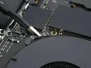
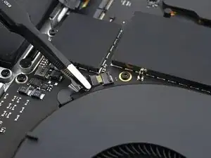
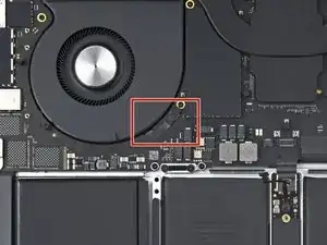
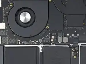
Use a spudger to gently pry up the locking flap on the ZIF connector for the right fan cable.
-
-
-
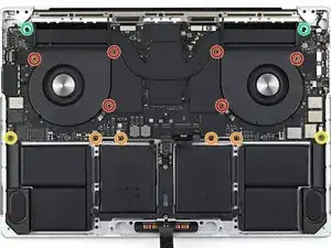
Use a T5 Torx driver to remove the ten screws securing the logic board to the frame:
-
Six 3.9 mm screws
-
Four 4.7 mm screws
-
Use a 4 mm Hex driver to remove the two 6 mm screws securing the logic board to the frame.
-
Use a T6 Torx driver to remove the two 6 mm screws securing the heat sink to the logic board and frame.
-
-
-
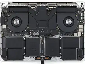
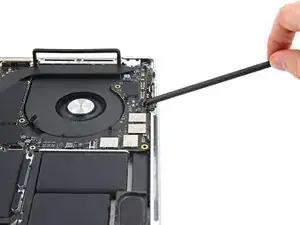
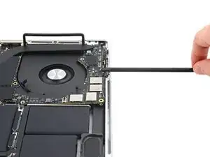
Insert a spudger between the right side of the logic board and the frame.
-
Pry up with the spudger to release the logic board from its clips.
-
-
-
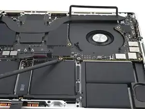
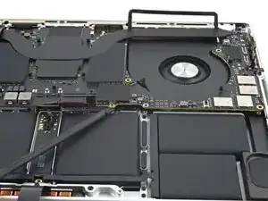
Insert a spudger between the bottom of the logic board and the frame.
-
Pry up with the spudger to release the logic board from its clips.
-
-
-
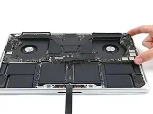
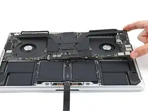
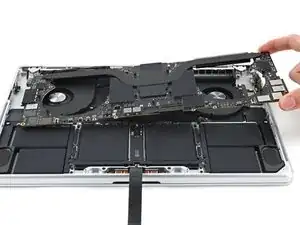
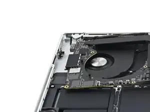
Gently lift up the logic board by its right side to release it from its alignment pegs.
-
Pull the logic board away from the left side of the device to separate the HDMI and SDXC ports from their slots in the frame.
-
Remove the logic board.
-
-
-
Make sure all 17 connectors are above the logic board before securing it back into the frame.
-
Hold the rubber spacers out of the way so the fins can drop into their recesses.
-
When reinstalling the logic board, insert the left side first to reposition the HMDI and SDXC ports.
-
Use your fingers to slightly compress the HDMI port to fit it into its recess. Otherwise, the logic board won't sit correctly.
-
-
-
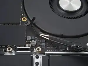
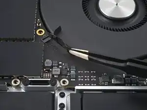
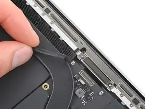
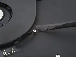
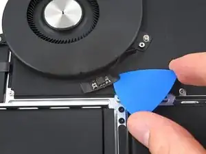
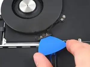
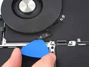
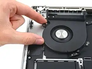
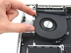
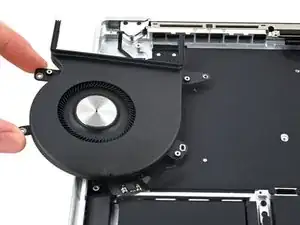
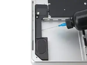
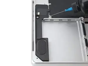
Insert the tip of an opening pick between the fan's cable and the frame.
-
Slice with the pick along the edges of the cable to separate the adhesive.
-
-
-
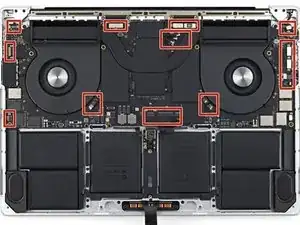
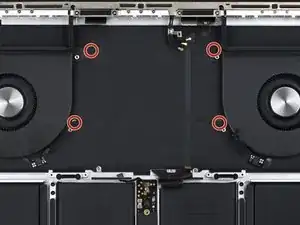
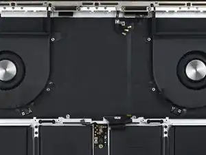
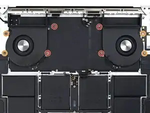
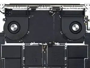
Remove the eight screws securing the fans to the frame:
-
Four 3.3 mm T3 Torx screws
-
Four 3 mm T5 Torx screws
-
-
-
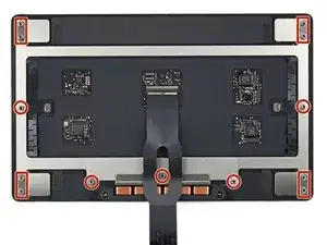
Use a T5 Torx driver to remove the 13 screws securing the trackpad assembly:
-
Ten 5 mm screws
-
Three 5.8 mm screws
-
-
-
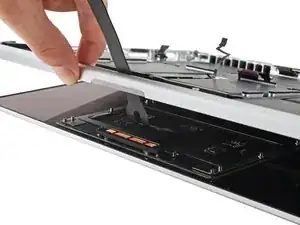
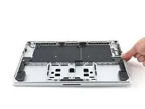
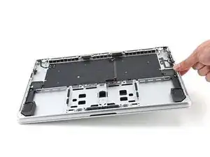
Swing the display open slightly, but keep the MacBook upside-down. The trackpad assembly should separate and lay flat on the display.
-
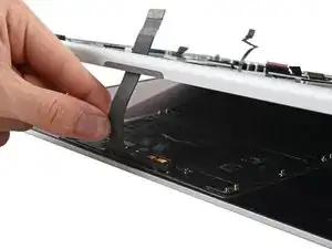
Carefully feed the trackpad's ribbon cable through its slot in the frame.
-
-
-
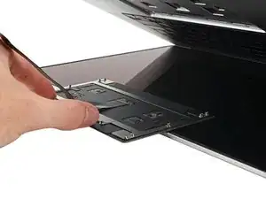
As you remove the trackpad assembly, be very careful not to lose the nine small metal washers resting on the screw posts. (They will fly off and get lost with very little provocation.)
-
Remove the trackpad assembly.
-
-
-
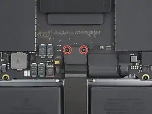
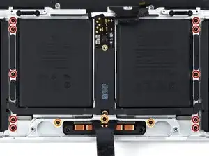
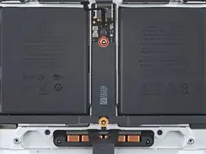
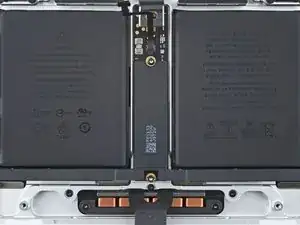
Use a T5 Torx driver to remove the two screws securing the battery board:
-
One 4.5 mm screw
-
One 3.8 mm screw
-
-
-
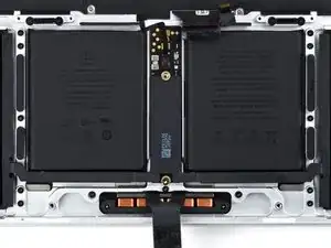
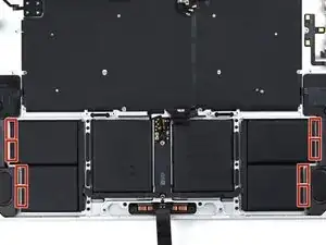
There are eight adhesive strips that are accessed from the bottom of the device.
-
There are six more adhesive strips accessed from the trackpad's location on the frame.
-
-
-
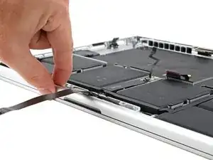
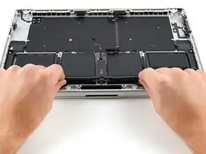
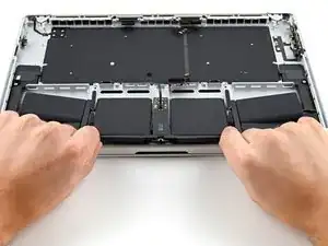
Pull the strip out slowly and steadily at a low angle. Give it plenty of time to stretch and un-stick from under the battery.
-
If the adhesive strip breaks off, try to retrieve it using your fingers or blunt tweezers, and continue pulling—but do not pry under the battery.
-
Repeat the process for all 14 stretch release adhesive strips.
-
-
-
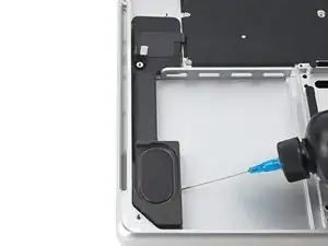
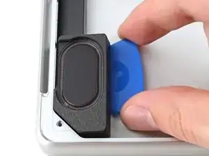
Apply a few drops of highly-concentrated isopropyl alcohol (>90%) along the inside edges of the speaker.
-
-
-
Tilt the right edge of the device upward to allow the isopropyl alcohol to work its way underneath the speaker.
-
Hold for 1–2 minutes to allow time for the isopropyl alcohol to weaken the adhesive.
-
-
-
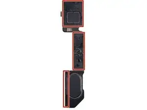
While you're waiting for the adhesive to loosen, note where the adhesive is located underneath the speaker.
-
-
-
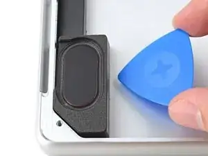
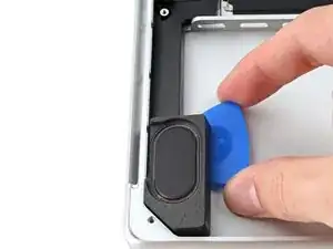
Slide the pick upwards to separate the adhesive along the bottom length of the speaker.
-
Leave the pick in to prevent the adhesive from resealing.
-
-
-
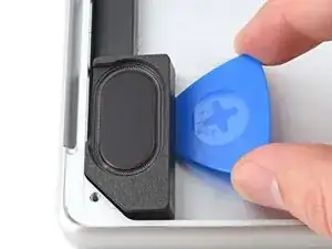
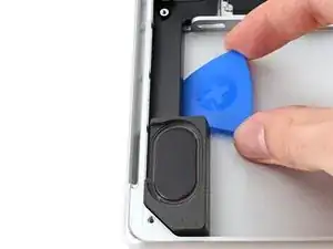
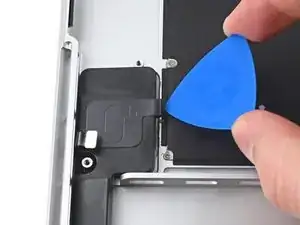
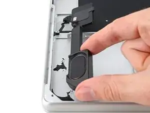
Pry up with the pick to completely separate the top adhesive.
-
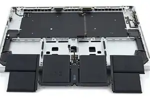
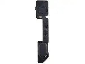
Remove the speaker.
-
Repeat the loosening and separating process for the other speaker.
-
Compare your new replacement part to the original part—you may need to transfer remaining components or remove adhesive backings from the new part before you install it.
To reassemble your device, follow these instructions in reverse order.
Repair didn’t go as planned? Try some basic troubleshooting, or ask our MacBook Pro 16" Late 2023 Answers community for help.