Introduction

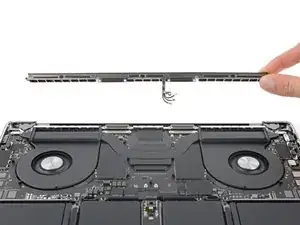
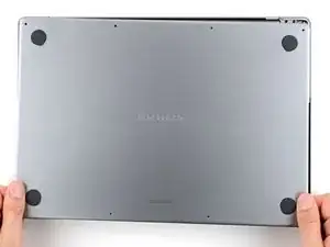
Use this guide to replace the antenna bar in your MacBook Pro 16" 2023.

If your battery is swollen, take appropriate precautions.

Some photos in this guide are of the previous model MacBook Pro and may contain slight visual discrepancies, but they won't affect the procedure.

  1. MElo1WJrYtdAY1cU
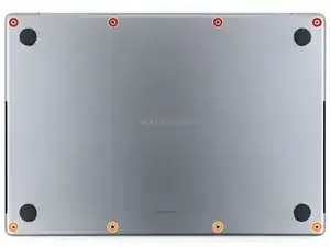
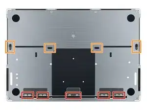
    • Use a P5 pentalobe driver to remove the eight screws securing the lower case:

    • Four 9.1 mm‑long screws

    • Four 6 mm‑long screws

    • Throughout this repair, keep track of each screw and make sure it goes back exactly where it came from.

  2. EMVn16dIXSnynasq
    EMVn16dIXSnynasq
    CvruIV6cgcERHVPu
    iWW3SZLcYO6DhLTF
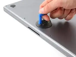
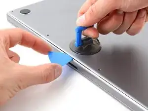
    • Apply a suction handle to the center of the lower case's front edge.

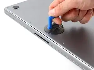
    • Pull up on the suction handle to create a gap between the lower case and the frame.

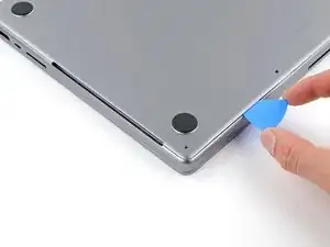
    • Insert an opening pick into the gap.

  3. VowKoKqQUTcJUW1Y
    VowKoKqQUTcJUW1Y
    BXFShFfEw3us3XYX
    tRxYm1oTMZ2VbiIM
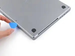
    • Slide your opening pick around the bottom right corner and up the right edge of the lower case.

    • If your pick gets stuck at the cutout, use your fingers to lift the lower case up slightly to allow your pick to slide underneath.

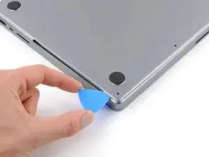
    • Slide your pick until it reaches the middle of the cutout, or until the rightmost clip stops it from sliding.

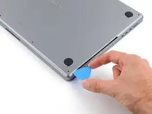
    • Twist your pick to release the two right clips.

    • You'll hear and feel a pop when each of the two clips releases.

  4. HpDiAZOlYlv3wWgh
    HpDiAZOlYlv3wWgh
    RZlpixTGXvHvkUcd
    5ofuLAdpsNnU5cJE
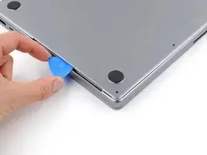
    • Slide your opening pick around the bottom left corner and up the left edge of the lower case.

    • If your pick gets stuck at the cutout, pry the lower case up slightly to allow your pick to slide underneath.

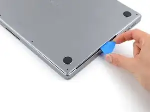
    • Slide your pick until it reaches the middle of the cutout, or until the leftmost clip stops it from sliding.

    • Twist your pick to release the left two clips.

    • You'll hear and feel a pop when each of the two clips releases.

  5. LHREHFMPXPennCxS
    LHREHFMPXPennCxS
    u6iVU2O1ASb5VFPY
    toTLPGIjhIL4THiP
    • Sliding clips along the back edge of the MacBook further secure the lower case. Separating these clips may require a lot of force—consider using gloves to protect your hands from the sharp edges of the lower case.

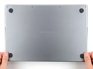
    • Firmly pull the lower case away from the back edge, one corner at a time, to disengage the sliding clips.

    • Keep the lower case flat to the MacBook. Don't pull upward until it's completely separated.

  6. XQYQqBTqQFYoVCoZ
    XQYQqBTqQFYoVCoZ
    QpCJcUDHqbNPZVk1
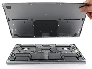
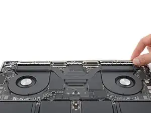
    • Remove the lower case.

    • To reinstall the lower case:

    • Lay it down and align the sliding clips with the back edge of the MacBook. Press down on the lower case and slide it toward the back edge to engage the clips.

    • When one side is engaged, it may push the other out of alignment. Check both sides as you push.

    • Once the back corners of the lower case are secured and flush with the frame, press down along the middle of the lower case to engage the four remaining clips.

    • You'll hear and feel each clip snap into place.

  7. JcOOIpGsWfqDMMmv
    JcOOIpGsWfqDMMmv
    YL6Y6wwsLwkXeZiJ
    1lHVOUPwGWrGncKG
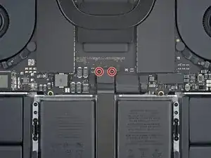
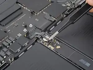
    • Use a T3 Torx driver to remove the two 2.1 mm screws securing the trackpad cable bracket.

    • Remove the bracket.

  8. Qc4GuMbcuMCL3SLS
    Qc4GuMbcuMCL3SLS
    QwiTu2ikpXKwaNKc
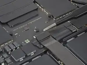
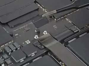
    • Use the flat end of your spudger to pry up and disconnect the trackpad cable press connector from the logic board.

    • To re-attach press connectors like this one, carefully align and press down on one side until it clicks into place, then repeat on the other side. Don't press down in the middle. If the connector is misaligned, the pins can bend and cause permanent damage.

  9. oeTgHAcLYWYcYeHS
    oeTgHAcLYWYcYeHS
    rBjK5quH3M3sfmXj
    pK1GcLMxaFsneyDx
    • The trackpad cable is lightly adhered to the battery board.

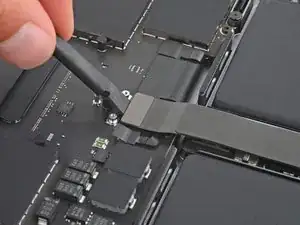
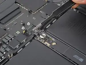
    • Peel the trackpad cable from the battery board.

    • Move the cable over the front edge of the MacBook.

    • Be careful not to crease the cable.

  10. pxWcWLWsSnhInhRx
    pxWcWLWsSnhInhRx
    xoYrIufNRWc1vqx2
    • Peel back the tape covering the battery data cable connector on the logic board.

  11. eGNLaxQdEbtAJmXL
    eGNLaxQdEbtAJmXL
    yYbnlPZWiDZhaAMH
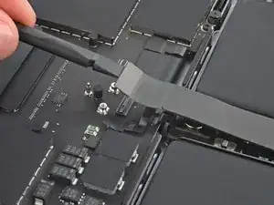
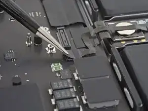
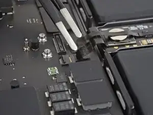
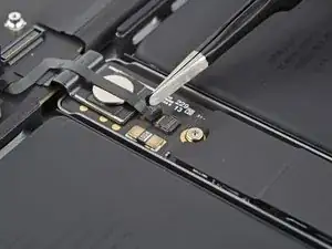
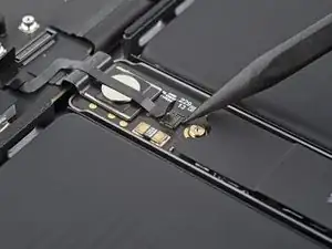
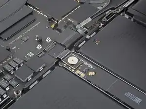
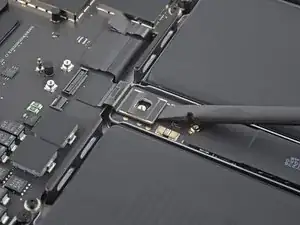
    • Use the point of a spudger or a clean fingernail to flip up the small locking flap on the battery data cable ZIF connector.

  12. meGcynWjFlcssBvR
    meGcynWjFlcssBvR
    CognANdCs4pyi4TJ
    IiMgwLToBvZsP1cx
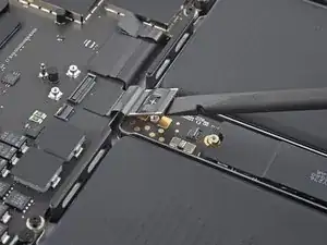
    • Slide one arm of your blunt nose tweezers under the battery data cable.

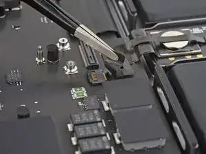
    • Grip the cable just below the head of the connector.

    • Slide the connector straight out of its socket.

  13. NGsyGhbUSbWICFZp
    NGsyGhbUSbWICFZp
    MYinewNtpNJ3r3Na
    • Peel back the tape covering the battery data cable connector on the battery board.

  14. BfQGmMdZbUNlUTkR
    BfQGmMdZbUNlUTkR
    RRoWSWQYJVoBFCTw
    YhwqdMUZL2ItpGPK
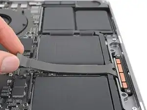
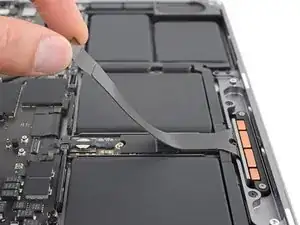
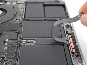
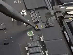
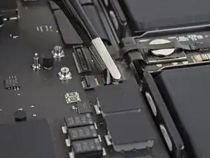
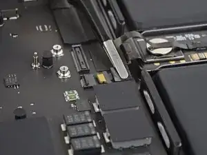
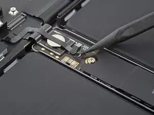
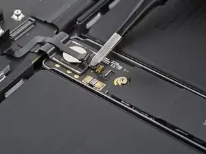
    • Use the point of your spudger or a clean fingernail to flip up the small locking flap on the battery data cable ZIF connector.

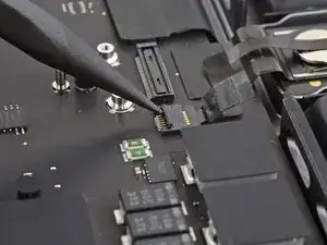
    • Use blunt nose tweezers to grab the battery data cable just under the head of the connector and slide it straight out of its socket.

  15. FmTwUfxVJu3cKwqI
    FmTwUfxVJu3cKwqI
    XPfLhUJuQ1POneUQ
    rbpHvx4LLyo5dl5h
    • The battery data cable is adhered to the battery board and logic board.

    • Peel the cable from the battery board and the logic board.

    • Remove the cable.

  16. SCPnnRC3SYHYfErs
    • Use a T5 Torx driver to remove the 3.9 mm pancake screw securing the battery connector.

  17. a2jJ4SCrLNXQmKAx
    a2jJ4SCrLNXQmKAx
    fBbCw3CeNrFC1qLm
    FnnxXRhXNC56QrGB
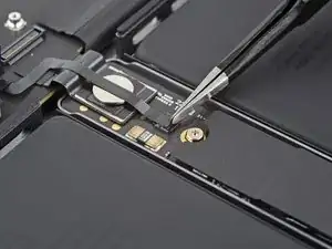
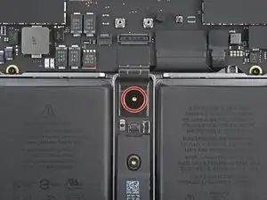
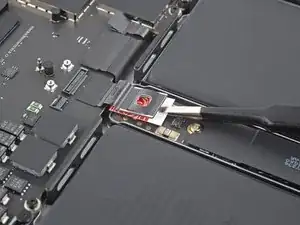
    • Use the flat end of your spudger to lift the battery connector away from the battery board, disconnecting the battery.

    • Lift the connector high enough that it doesn't accidentally make contact during the repair, but no more than 45 degrees to prevent damaging its hinge.

    • For added safety, place a barrier, such as a piece of a playing card, between the connector and board.

  18. EcnfpjOKivQfM23W
    EcnfpjOKivQfM23W
    XRY23AXCQJX3AauM
    G3OjddxcGWtGPcKV
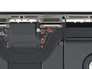
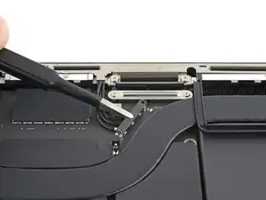
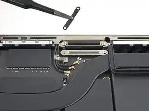
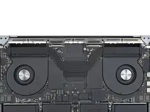
    • Use your T3 Torx driver to remove the three 2.1 mm screws securing the antenna cable cover and bracket.

    • Remove the antenna cable cover.

  19. txVJmKChHhD5savp
    txVJmKChHhD5savp
    1UEsuIC1w2AOgn6x
    3W1ZZgJBTROapLFC
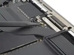
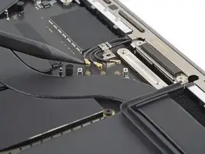
    • Use the point of your spudger to pry up and disconnect the three antenna cables from the logic board.

    • Pry only on the metal heads of the connectors. Avoid prying on the cables themselves.

    • To reconnect antenna cables like these, hold each one in place over its socket and press down with the flat end of your spudger. The connector will snap into place.

  20. tCtJPjQyMenKtmnG
    tCtJPjQyMenKtmnG
    4Aokx2plbOOFqpxg
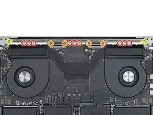
    • Use a P2 pentalobe driver to remove the nine 1.5 mm screws securing the antenna bar.

    • Due to their small size, these screws strip very easily. Make sure your driver is in good condition. Keep it vertical and apply constant downward pressure as you loosen the screws.

    • During reassembly, don't overtighten these screws—ensure that they're threading in properly, then tighten only until they're snug.

    • Use your T5 Torx driver to remove the six remaining screws securing the antenna bar:

    • Four 3 mm screws

    • Two 7.5 mm screws

  21. xO2D3IUQCHpnORPr
    xO2D3IUQCHpnORPr
    dALubd6fgN6UpGyo
    • Pull the antenna bar straight up and out of the frame to remove it.

    • If it feels stuck, use the point of a spudger to pry it up from the frame.

Conclusion

To reassemble your device, follow these instructions in reverse order.

Take your e-waste to an R2 or e-Stewards certified recycler.

Repair didn’t go as planned? Try some basic troubleshooting, or ask our Answers community for help.

Clay Eickemeyer

Member since: 19/09/22

65190 Reputation

0 comments