Introduction
-
-
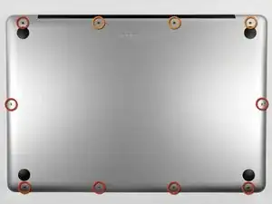
Remove the following ten screws securing the lower case to the upper case:
-
Three 13.5 mm (14.1 mm) Phillips screws.
-
Seven 3 mm Phillips screws.
-
-
-
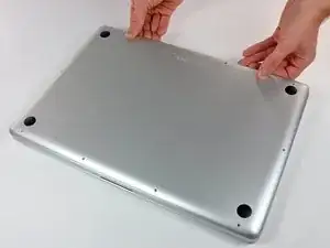
Using both hands, lift the lower case near the vent to pop it off two clips securing it to the upper case.
-
Remove the lower case and set it aside.
-
-
-
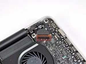
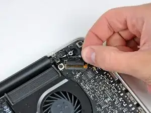
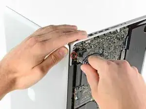
Use the edge of a spudger to pry the battery connector upwards from its socket on the logic board.
-
-
-
Bend the battery cable slightly away from its socket on the logic board so it does not accidentally connect itself while you work.
-
-
-
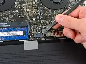
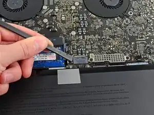
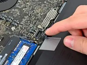
Use the flat end of a spudger to carefully pry the AirPort/Bluetooth ribbon cable up off its socket on the logic board.
-
-
-
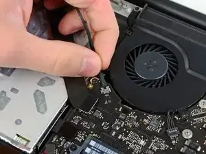
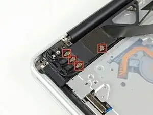
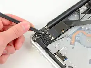
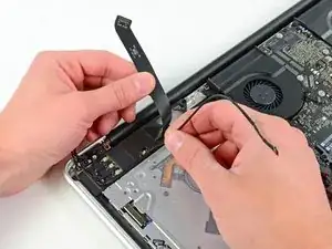
Use the tip of a spudger to pry the four antenna connectors up from their sockets on the AirPort/Bluetooth board.
-
-
-
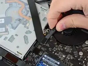
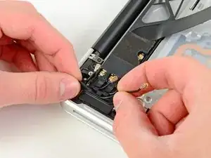
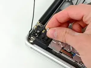
De-route all four antenna cables from their channels in the AirPort/Bluetooth housing.
-
De-route the camera cable from its channel in the AirPort/Bluetooth housing.
-
-
-
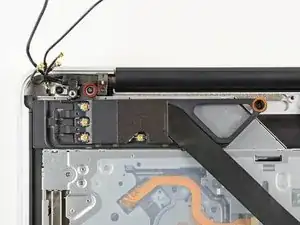
Remove the following two screws securing the AirPort/Bluetooth assembly to the upper case:
-
One 8.6 mm Phillips screw
-
One 3.9 mm Phillips screw
-
-
-
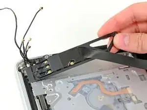
Remove the AirPort/Bluetooth assembly from the upper case, minding any cables that may get caught.
-
-
-
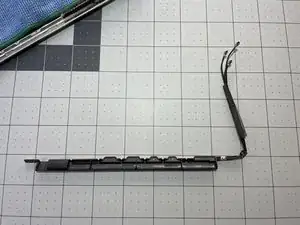
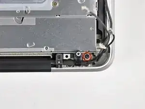
Remove the 8.6 mm Phillips screw securing the antenna/camera cable retainer to the upper case.
-
Remove the antenna/camera cable retainer from the upper case.
-
-
-
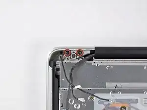
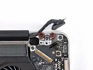
Remove two of the three 6 mm T6 Torx screws securing the right side of the display to the upper case.
-
-
-
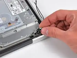
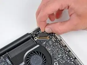
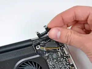
Grab the plastic pull tab secured to the display data cable lock and rotate it up and over the connector, toward the DC-In side of the computer.
-
Pull the display data cable straight back (not up) out of its socket on the logic board.
-
-
-
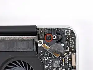
Remove the 8.6 mm Phillips screw securing the display data cable retainer to the upper case.
-
Remove the display data cable retainer from the upper case.
-
-
-
Remove two of the three 6 mm T6 Torx screws securing the left side of the display to the upper case.
-
-
-
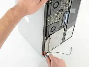
Open your MacBook Pro so the display is perpendicular to the upper case.
-
Place your opened MacBook Pro on a table as pictured.
-
While holding the display and upper case together with your left hand, remove the remaining T6 Torx screw from the upper display bracket.
-
-
-
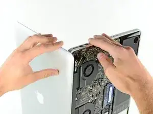
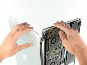
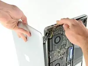
Grab the upper case with your right hand and rotate it slightly toward the top of the display so the upper display bracket clears the edge of the upper case.
-
Rotate the display slightly away from the upper case.
-
Lift the display up and away from the upper case, minding any brackets or cables that may get caught.
-
-
-
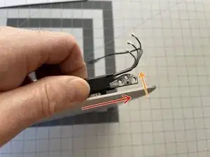
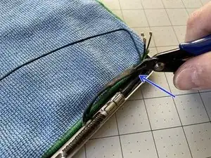
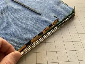
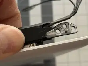
Starting on the right side of the display, slide the antenna's plastic cover approximately 1/4" to the right.
-
Then, lift up the right edge of the plastic cover just enough to separate it from the display.
-
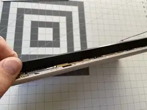
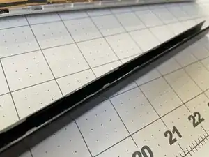
Continue lifting the cover along its length, until the entire cover is separated.
-
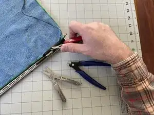
Remove the plastic cover and retain for reassembly.
-
-
-
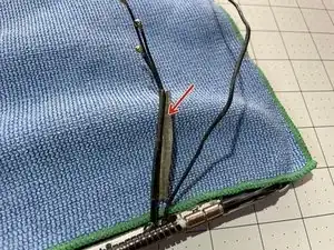
Unwrap the black tape to separate the iSight camera cable from the Airport/Bluetooth cables.
-
If unwrapping is not possible, carefully cut the black tape lengthwise, making sure not to accidentally cut any of the cables -- especially the iSight cable.
-
-
-
Optional: Place a cover on top of your display, just in case your screwdriver slips.
-
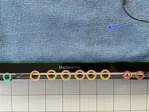
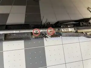
Remove the two #000 Phillips screws on the far-right (see detail photo).
-
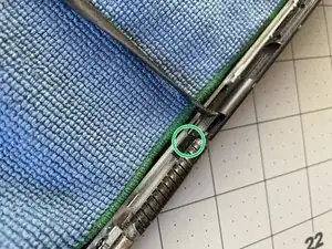
Remove the somewhat-hidden #000 Phillips screw on the far-left of the display (see detail photo).
-
Remove the six #000 Phillips screws in the middle of the antenna board.
-
-
-
Make sure to re-wrap the Antenna/iSight cables back with some tape. If your replacement part did not include any, reuse the one you took off. My replacement part came with tape, but I still put a bit of Kapton tape around the black tape to completely close the fold.
-
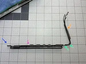
The new antenna hopefully came with the small grounding straps that go around the cables, and get screwed in on the far-right of the display. If they didn't, you'll need to remove them from the old antenna.
-
Insert the replacement board starting with the far-left side. Once inserted, the board should sit loosely in the grooves of the display.
-
When installing the new antenna, first screw in one of the six center screws -- that will help align the far-left screw over its hole.
-
To reassemble your device, follow these instructions in reverse order.

One comment
The last steps are pointless, I've followed every single step, and now I'm stuck because I have no idea how to install the piece featured in this guide, with the one we just unmounted. I'm so upset you can't imagine..,.
A.R -
Step 1 (technically step 9 - replacing the base plate) Apparently one of my screws was a micron or two smaller than the others. This screw belongs to the hole above the optical drive, which is also apparently a couple of microns smaller than the others. It took seven attempts to figure which screw had originally been in that hole; all the other screws were too large, but fitted perfectly everywhere else.
Bizarre much?
Will -
It might be a matter of how the screws are driven in, and not that they're slightly different sizes. When I reassembled my MacBook, a couple of the screws, including the one over the optical drive you mention, were hard to drive in and jutted up a little bit instead of sitting entirely flush. Swapping screws didn't help. The solution was to unscrew them and drive them in at a bit of an angle - perpendicular to the slightly curved surface of the back plate where the screw holes were, instead of fully vertical with respect to the ground the Macbook is sitting on. Doing it that way, the screws were easier to drive in and they all ended up flush in their holes. Didn't matter which screws they were. (I swapped a few around just to check after reading this.)
Andrew Janke -
I had no such screw issues. Either there are differences in manufacturing lots or I just got incredibly lucky during reassembly!
xtophr -
I discovered a great way of organizing the screws. I used an ice cube tray and added the screws in order, keeping the different kinds together. So when it came to reversing the steps, the screw order was an added control step to returning everything in its place.
leonie -
Great advise! Love it! :)
Ririds -
I used to do that and that worked really great until I bumped it by accident and the entire tray went on the rug! I spent the next day sorting things out.
Now I use these:
http://www.sciplus.com/p/50-114-CLEAR-PL...
The lower ones 50 to a package. I mark them w/ blue tape. Often if it's part like the fans, or the optical drive I'll tape the screws into/near the holes where they belong. I did this a lot especially w/ the bottom screws from MBPs until I'd done so many I knew exactly where the longer ones went.
Richard Sato -
I wrapped the screws in a piece of blue masking tape and wrote the number on the little pouch I made. Then I stuck the blue tape pouches on the underside of the case bottom in order.
Roscoe -
I take double-sided tape, put that on a piece of paper, stick the crews to that, and label them.
jelimoore -
Best I've found is a bead sorting tray. They're like $5 at Wal-Mart and they have a lid that seals up and won't let them jump between containers.
maccentric -
I take a sheet of paper, pierce the screws through the paper, take a pen and box the screws and write out what step they belong to.
Nils -
@Will, in my case I had the same result as you did. As a reminder to myself the next time I need to open the computer, I put a dot of white paint on those two screw's head and a very, very thin ring of white on the very edge of each hole, that way I'll know they go into those two holes.
Roger -
Actually the four screws on the bottom were not threaded all the way up. I didn't check to see if the thread gauge was the same on them, but it wasn't until I had about four screws out (I didn't take them out in the order that the bottom all came out first) that I noticed a difference. I then took out the rest of the bottom ones to see if they matched the two that were already out that weren't threaded to the top. They did. So I went under the assumption that those were all bottom screws and when I put it back together everything went fine with no resistance.
So there are three types of screws: Four for the bottom, three long ones as indicated and three others that might be slightly smaller than the bottom ones.
wresnick -
Hi,
Although its more than a year since your contribution, I thought you might be amused to know that it is not just that the screws go in more easily when at an angle, Apple actually drilled and tapped the holes at a 15% angle. I too had tried to drive them in straight. An Apple "genius" - I was in for something else - clarified the design for me. It was done so that the screws lay flush on the angled part of the lower case. Nice design, but since Apple encourages DIY memory and drive changes, they could have mentioned this little ... trap.
H Stahl -
MacBookPro8,2
Intel Core i7, 2,2 GHz, RAM 16 GB
Mountain Lion
May someone help me?
I have installed the second drive with ssd 840 evo, but when I try to copy the file from the new drive to the main hd this in not allowed (errore -36)
Piero -
To my knowledge you can't transfer a single file more than 4gb. I advise compressing to a bunch of rars to split the file size and moving them individually
1982sketcher -
Hey everyone, here's the very best way to PERFECTLY organize your screws AND keep track of the order of the procedure: Get a piece of plain corrugated cardboard and a pen (I like using a Sharpie). For EACH step of the disassembly, draw a simple diagram of the layout of the computer on the piece of cardboard, with dots or Xs where the screws are located. Right after you remove each screw from the computer, poke a hole in the cardboard in its corresponding diagram position with your screwdriver and place the screw in that hole. If there are other non-screw related parts to be removed, you can add notes below each step diagram to remind you of where they go or how they should be placed. This cardboard method is great not only because your screws will not go flying or get mixed up by accident if bumped, but each screw goes EXACTLY back where it came from and you can keep the cardboard as a template for future use if necessary!
- zerø K
zeroK -
a video of these steps
https://www.youtube.com/watch?v=SS9is40C...
julie56 -
These instructions worked great for me. I ordered a replacement battery from Key Power (on Amazon) for my 15" Macbook Pro (mid-2010). Cost was $74 shipped.
Battery came with 3 different screwdrivers to help with installation. I just needed the one size though, since my 2010 seemed to use all the same size screws.
Thanks!
Marcos -
During re-assembling (put the screws back in), it is important to note that the 3mm threaded holes are not completely vertical, but bent a little bit such that the hole direction is rectangular to the tapered surface. The force of the screwdriver must point towards the direction of the hole. Otherwise the screw gets jammed
kusi -
There is a FOOLPROOF WAY TO ORGANIZE ALL SCREWS and other parts removed.
Print the repair guide.
Yes, the actual photo of the bottom of the laptop with the circles around the screws.
When you remove the screw, tape it to the photograph.
You will tape the screw to the exact location that you just removed it from.
Same thing with any part you remove.
splashzoneent -
Thanks Splash!!! I used your suggested method, and it was perfect: kept all my screws, and i was able to, very easily, put them back in their correct place. I greatly appreciated your feedback. Thank you for sharing!!
Tommy Kedar -
Thank you!!! This worked fabulously - even the I.T. people at my workplace were excited as they never thought to do that before. Replacing the battery took about 10 minutes!
nclarke36 -
Worked like a charm! Took less than 20 minutes.
It's Oct. 2015, and the fan cost me about $10. it was the same brand/model...
SUNON MG62090V1-Q020-S99 .
SOME TRICKS -
1- no T6 screwdriver- was careful using needle nose players to loosen 2 screws protruding up, then use a small phillips to push real hard into the T6 slots, SLOWLY turn , also used a small flat head screwdriver (for eye glass repair) was able to grab thread on T6's, made a small mark with screw driver across the top so I could see when it started to turn.
2- no spudger -made one; cut a little strip 1/2" x 1 1/2" of plastic. couldn't get it to slide under plug, there's an edge where plug fits. so lifted old fan out, pulled upward on the plug it popped right out with very little effort. I used my home made spudger to push the new plug into place.
3- download free "Macs Fan Control" This is how I was alerted to the fan not working in the first place. Program shows temperature of all key components in the computer.
cheers- Durango CO!
Dgodrummer -
Watch the video first, read the entire tutorial and all the comments before you start, and spread a white towel on the floor so you can find screws when you drop them. Watch this first -- http://www.youtube.com/watch?v=qiBxhA29e...
kevicoll409 -
The link above is no longer available.
Kristina Graham -
I will be buying a battery from you and using your instructions. I just installed a new CD/DVD using your instructions and 1) I feel like I owe you something and 2) Although more expensive, I have the confidence your battery will work. My current battery is the original with 1399 cycles in 7.2 yrs. A tech buddy had bought me a replacement and I installed it. I had just installed a new OS and the kernel_task went going nuts, using 90% of the CPU. Hours on the phone with Apple did not resolve the issue. On a whim, I put the old battery back in and Voila! But I cannot risk my battery swelling and going south on me. I am also going to buy your installation tools. Yeah, I already have them. But you can never have enough tools…or beer. And you don’t sell beer.
Pete Banks -
The instructions say that I am removing PH00 screws. I found that my MBP, mid ‘12, Retina has pentalobe screws instead!
jsandersonq -
This laptop definitely originally shipped with Phillips screws—but, Apple has been known to replace Phillips screws with pentalobes when one of their devices is brought in for service. Sorry for the rude surprise! Fortunately the correct driver is easy to find nowadays. [Blatant self-promotion alert!] If you support free repair manuals, consider picking one up from iFixit. Good luck!
Jeff Suovanen -
Me, too, and it’s plausible that this machine has been serviced by Apple in the past, replacing the screws as Jeff Suovanen suggests.
iFixit shipped a pentalobe bit with the kit, but it’s too large for the actual screws, so it looks like I now need to get another bit. But what size?
Jeff’s link is to a driver with a P5 bit, and that page links to a P2 screwdriver, but since I don’t know what size I actually need (and I don’t have a micrometer to hand) I’m reluctant to buy two on spec.
Norman Gray -
(The bit in the kit appears to be a P6, so I’m inclined to order a P5 and see what happens)
Norman Gray -
You’re using the wrong repair guide. This guide is for the 2012 NON-Retina MBP. You have a Retina MBP. The stock case screws in the 2012 NON-Retina are all Phillips, just as the guide says.
Steven Wymor -
To keep track of screws, I used the suggestions above by taping a photo of the lower case to a piece of corrugated cardboard and inserting/taping the screws in place. Also, as some have noted, the screws go back in at a slight angle; they are angled toward the center of the unit.
Kristina Graham -
If your vision, like mine, is getting too fuzzy to be able to distinguish between a tiny Phillips screwdriver and a tiny Tri screwdriver, there’s an easy way. With a Phillips (or a Pozidrive) you can get two opposite wings to reflect the light from a lamp or window straight towards your eye at the same time. With a Tri (or Penta) you can only get one wing to reflect at a time, however much you twiddle it.
Alan Waller -
There’s a very easy way to avoid cross-threading a screw thread, any size.
Put the screw into its hole and start by turning it gently, slowly BACKWARDS. When you hear a little “Click!” sound, the male thread has just passed the opening in the female thread and is in exactly the right position to enter into it correctly when you start to turn in the correct forward direction.
Remember, all drivers except hex (Allen key) and TorX need pressure to avoid slipping out and damaging the head. So even when you want to turn it in with LOW moment/torque, keep the CONTACT PRESSURE high.
Alan Waller -
The keep the pressure on is on point. In my case once I loosened my first screw I thought I could relief my initial pressure. It was a mistake. I was doing the whole thing very slowly as a precaution. That helped me notice that the Phillips screw driver was sliding up out of the screw head. Not being sure why, I put pressure back on the screw driver until almost all the screw was out of the hole. Once out, I examined closely to find out that the threads have some sort of coating. It looks to me like some kind of locktite. Then I understood the importance of keeping the pressure on all the way through. It made me uneasy having to keep so much pressure on such tiny screws, but I found it was the only way to prevent damage to the “slots” on the heads. Anyway, all of them suffered some degree of damage, but I was able to successfully remove them and reinstall all of them back in their original holes.
Martin Mejia -
After reading this page on iFixit several times, I just could not face all the work of replacing the Logic Boards on two MacBookPro 2011s even if I was prepared to pay approx 400 USD (which I wasn’t). Then I read the reviews of a couple of folks who’d stripped down their machines and put their logic boards in the oven and, it worked! I wondered, if I just used my new Steinel Hot Air Tool (heat gun in my language) recently delivered from iFixit, on the logic board in-situ, without removing it? So I removed the battery, hard drive, and RAM and unplugged all the leads I could see WITHOUT removing anything else physically. Then using the 500 degrees set on the gun (setting 2) I ‘played’ the gun over the logic board for about 60 seconds on machine one with the restart problem (plus latterly, not completing start-up). Long story short… it worked! I spent a long time getting the s/w to load, but the commentary is too short to let me relate that part… ping me if I can help you do the same! blackaye@gmail.com
Ian Black -