Introduction
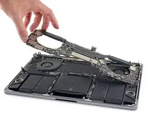
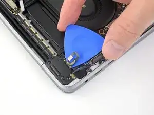
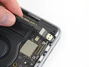
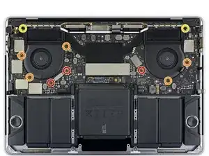
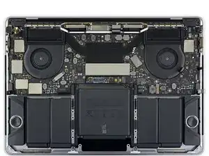
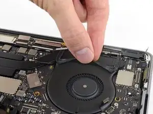
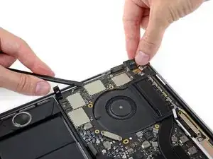
Prerequisite only—remove the logic board and heat sink together as a single assembly, either for further disassembly or simply to get it out of the way.
-
-
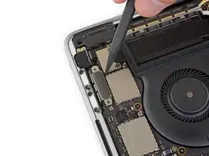
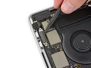
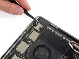
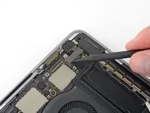
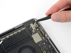
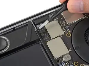
Use a spudger to disconnect the keyboard connector by prying it straight up from the logic board.
-
-
-
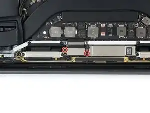
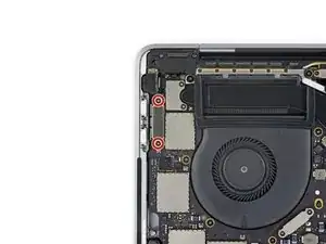
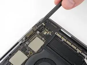
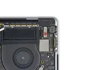
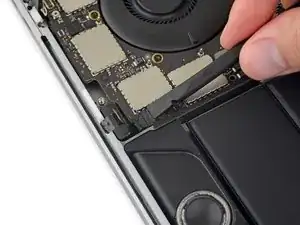
Remove the two 2.9 mm T3 Torx screws securing the aluminum cover on top of the main display cable.
-
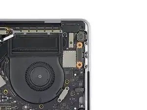
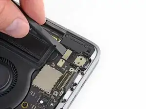
Remove the cover.
-
-
-
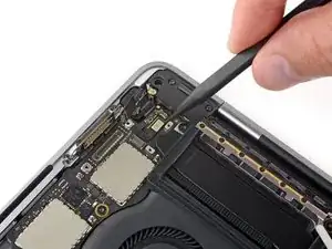
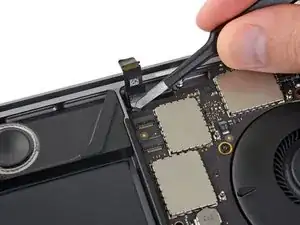
Remove the two 1.7 mm T3 Torx screws securing the aluminum cover on top of the display cable flex connector.
-
Remove the cover.
-
-
-
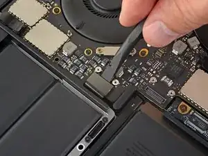
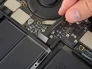
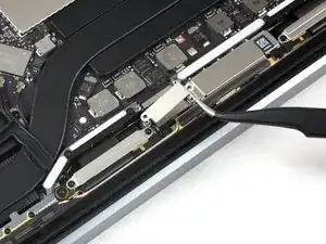
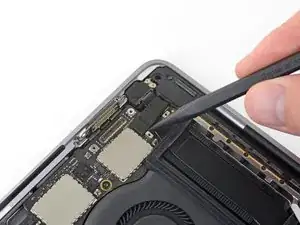
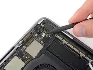
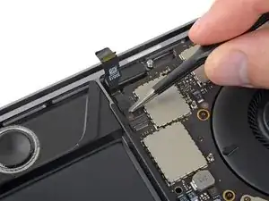
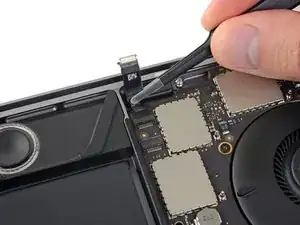
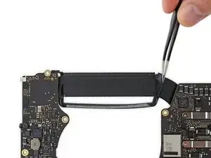
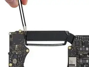
Pry the display board flex cable straight up from its socket to disconnect it from the display board.
-
-
-
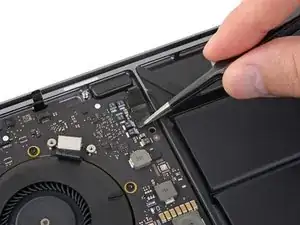
Using a T3 Torx driver:
-
Remove two 1.4 mm screws from the Thunderbolt port connector bracket on the left.
-
Remove two more 1.4 mm screws from the Thunderbolt port connector bracket on the right.
-
-
-
Use a spudger to disconnect the left-side Thunderbolt port connector by prying it straight up from the logic board.
-
Gently push the connector aside so it won't interfere with logic board removal.
-
-
-
Repeat for the right-side Thunderbolt port connector, prying it up from the inside edge and pushing it carefully aside.
-
-
-
Use a T3 Torx driver to remove the two 1.9 mm screws from the cover bracket securing the Touch ID and 3.5 mm audio jack connectors.
-
-
-
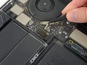
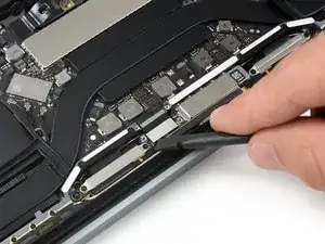
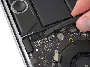
Use a spudger to disconnect the 3.5 mm audio jack flex cable by prying it straight up from the logic board.
-
Gently push the flex cable aside.
-
-
-
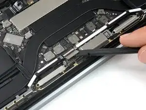
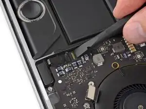
Disconnect the Touch ID and power button flex cable by prying it straight up from the logic board.
-
-
-
Apply mild heat using an iOpener, heat gun, or hair dryer to soften the adhesive under the power button/Touch ID flex cable.
-
-
-
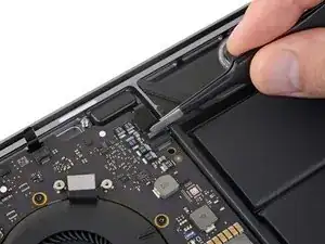
Carefully slide an opening pick under the flex cable to separate it from the logic board, and push it carefully aside.
-
If you have trouble, don't force it—apply a little more heat and try again.
-
-
-
Use a T3 Torx driver to remove the 1.9 mm screw from the Touch Bar digitizer connector bracket.
-
-
-
Use a spudger to disconnect the Touch Bar digitizer by prying its connector straight up from the logic board.
-
-
-
Use a T3 Torx driver to remove two 1.9 mm screws from the Touch Bar display connector bracket.
-
-
-
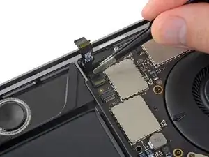
Use a spudger to disconnect the Touch Bar display connector by prying it straight up from the logic board.
-
-
-
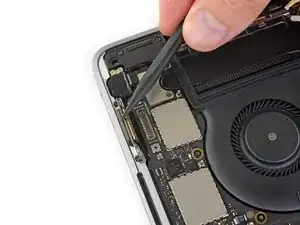
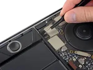
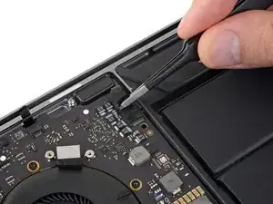
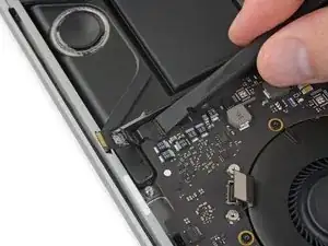
Open the locking flap on the microphone cable's ZIF connector by prying it straight up from the logic board.
-
-
-
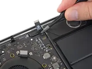
Disconnect the microphone cable by pulling it back—away from the fan—until it slides out of its socket.
-
If possible, pull on the attached tape, rather than on the cable itself.
-
-
-
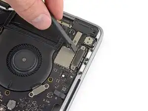
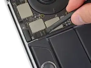
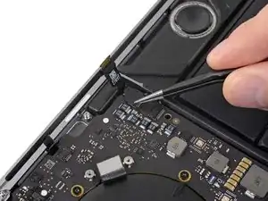
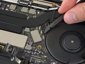
Flip open the locking flap for the left-side tweeter ZIF connector by prying it straight up from the logic board.
-
-
-
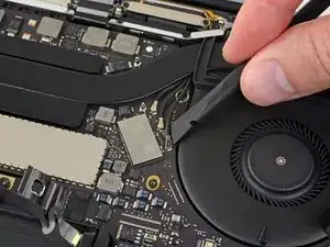
Disconnect the cable by pulling it towards the tweeter until it slides out of its socket.
-
If possible, pull on the attached tape rather than the cable itself.
-
-
-
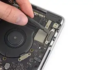
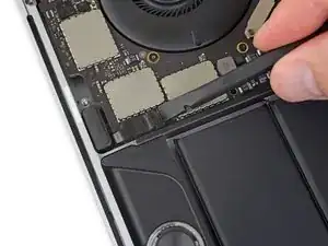
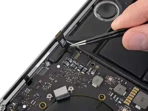
Flip open the locking flap for the left main speaker ZIF connector by prying it straight up from the logic board.
-
-
-
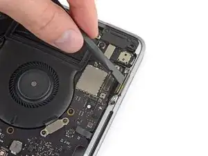
Disconnect the left main speaker cable by pulling it toward the tweeter until it slides free from its socket.
-
Remember to pull on the attached tape, not the cable.
-
-
-
Repeat the previous six steps to disconnect the opposite tweeter and main speaker, on the right.
-
Begin by peeling back any tape covering the tweeter connector.
-
-
-
Flip open the locking flap for the right-side tweeter ZIF connector by prying it straight up from the logic board.
-
-
-
Disconnect the cable by pulling it towards the tweeter until it slides out of its socket.
-
Remember to pull on the tape if possible—not the actual cable.
-
-
-
Flip open the locking flap for the right-side main speaker ZIF connector by prying it straight up from the logic board.
-
-
-
Pull the right-side main speaker cable toward the tweeter until it slides free from its socket.
-
-
-
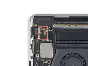
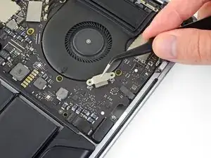
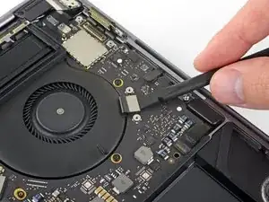
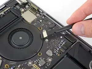
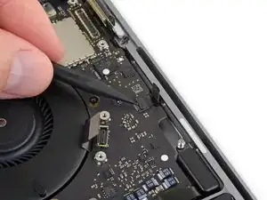
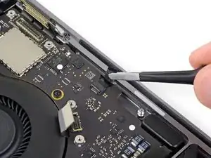
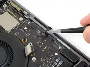
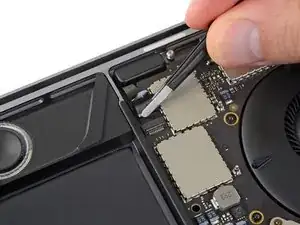
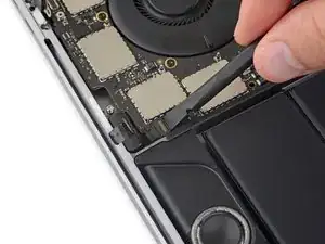
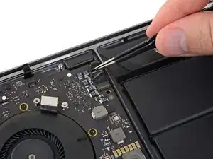
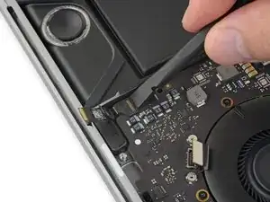
Disconnect the first antenna cable by prying it straight up from its socket.
-
Carefully slide your tweezers or the flat end of your spudger underneath the cable until it's near the socket, and then gently twist or pry up to disconnect it.
-
-
-
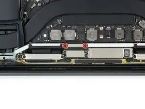
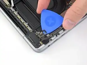
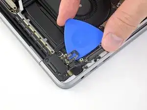
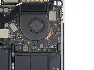
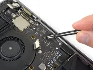
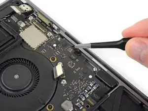
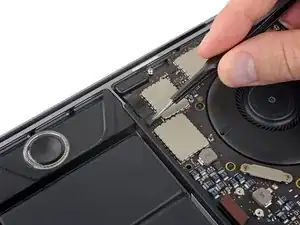
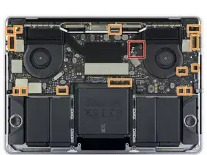
Remove all ten screws securing the logic board assembly:
-
Three 2.5 mm Torx T3 screws
-
Five 2.9 mm Torx T5 screws
-
Two 3.0 mm Torx T5 screws
-
-
-
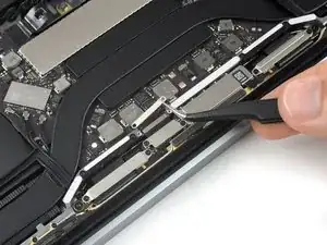
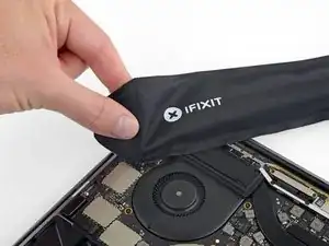
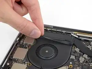
Peel up (but don't remove) the two rubber vibration damping strips from the adhesive holding them to the fans.
-
If needed, apply mild heat with an iOpener, hair dryer, or heat gun to soften the adhesive and make the dampers easier to separate.
-
-
-
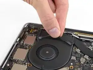
Check the alignment of the rubber vibration dampers, and adjust them as needed.
-
Feed the antenna cable bundle through the gap between the logic board and heat sink, and make sure it lines up correctly as you lower the board into place.
-
Verify that no cables get trapped under the board as you install it. Check each marked location carefully.
-


To reassemble your device, follow these instructions in reverse order.

One comment
Microphoneのパーツの説明欄には、Teardownの動画がリンクされていますが、その動画にはMic部分の説明が無いため、このページをリンクしておくと良いと思いました。
This page should be linked In the page of microphone assembly. Threre is not any microphone assembly part in the video embedded in the page.
polo -
T4 worked best here for me.
Benjamin Bradshaw -