Introduction
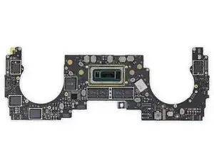
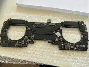
This guide will take you through the steps of replacing the logic board in your 2018/2019 (A1989)MacBook Pro.
-
-
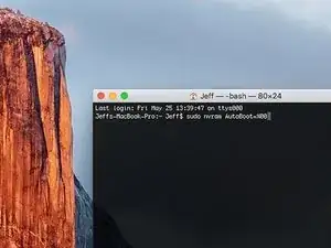
Power on your Mac and launch Terminal.
-
Copy and paste the following command (or type it exactly) into Terminal:
-
'sudo nvram AutoBoot=%00
-
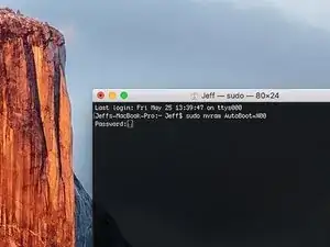
Press [return]. If prompted, enter your administrator password and press [return] again. Note: Your return key may also be labeled ⏎ or "enter."
-
sudo nvram AutoBoot=%03
-
-
-
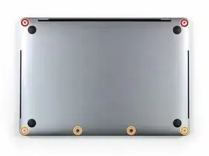
Use a P5 Pentalobe driver to remove the six screws securing the lower case:
-
Two 6.2 mm screws
-
Four 3.4 mm screws
-
-
-
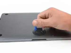
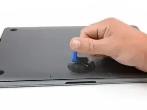
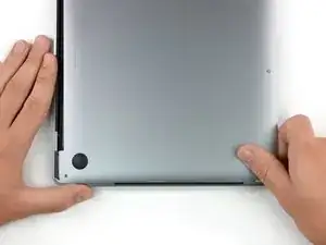
Apply a suction handle to the lower case near the front-center area of the MacBook Pro.
-
Lift the suction handle to create a slight gap between the lower case and the chassis.
-
-
-
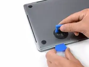
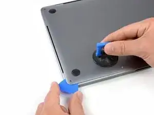
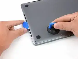
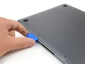
Insert one corner of an opening pick into the space between the lower case and the chassis.
-
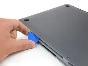
Slide the opening pick around the nearest corner and halfway up the side of the case.
-
-
-
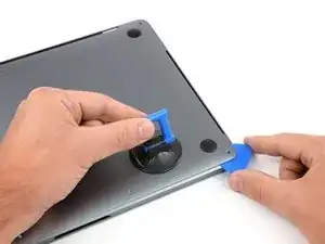
Repeat the previous step on the opposite side, sliding your opening pick under the lower case and up the side to pop the second clip free.
-
-
-
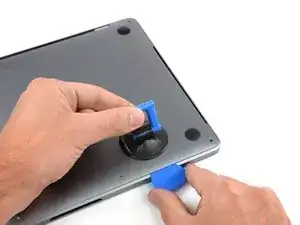
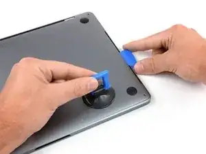
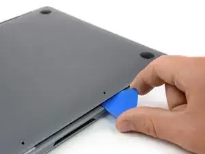
Insert your opening pick once again under the front edge of the lower case, near one of the two centermost screw holes.
-
Give the pick a firm twist to pop free the third clip securing the lower case to the chassis.
-
Repeat this procedure near the other of the two centermost screw holes, popping the fourth clip free.
-
-
-
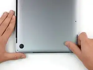
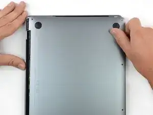
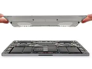
Pull the lower case firmly towards the front of the MacBook (away from the hinge area) to separate the last of the clips securing the lower case.
-
Pull first at one corner, then the other.
-
-
-
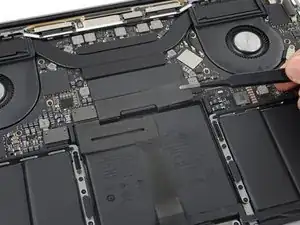
Carefully peel up the large piece of tape covering the battery connector, on the edge of the logic board nearest the battery.
-
Remove the tape.
-
-
-
Disconnect the battery board data cable by sliding it out from its socket.
-
Slide parallel to the logic board, in the direction of the cable.
-
-
-
Use a T5 Torx driver to remove the 3.7 mm pancake screw securing the battery power connector.
-
-
-
Use a spudger to gently lift the battery power connector, disconnecting the battery.
-
Lift the connector high enough so that it stays separated from its socket. If it accidentally makes contact during the course of your repair, it could damage your MacBook Pro.
-
-
-
Use a T3 Torx driver to remove the two 1.8 mm screws securing the trackpad cable connector bracket.
-
-
-
Use a spudger to disconnect the trackpad ribbon cable by gently prying its connector straight up from the logic board.
-
-
-
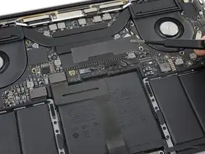
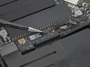
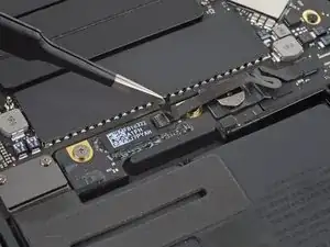
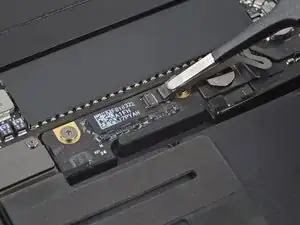
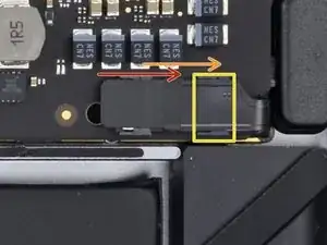
Carefully peel back the black tape to reveal the ZIF connector.
-
Unlatch the ZIF connector by flicking the arm on the connector upwards and carefully remove the cable from the connector by sliding it out.
-
Repeat this process with the newly revealed connector.
-
-
-
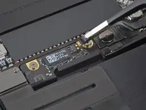
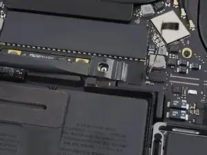
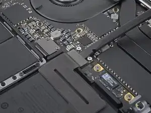
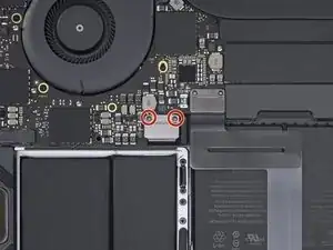
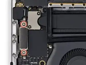
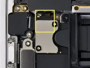
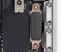
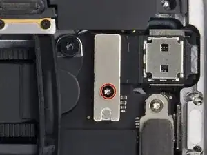
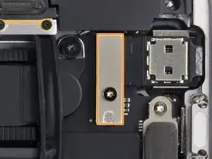
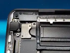
Use a T3 Torx driver to remove the two screws.
-
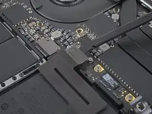
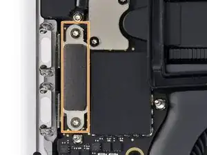
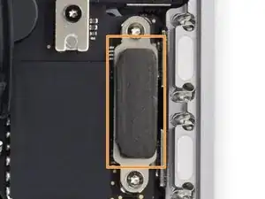
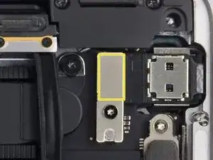
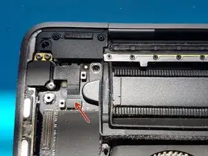
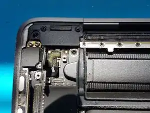
Once the screw have been removed carefully remove the metal shield.
-
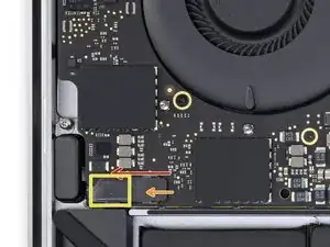
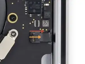
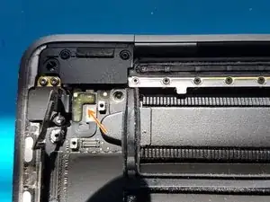
Under the metal shield there is a connector, carefully unplug it.
-
-
-
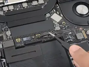
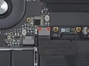
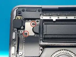
Use a T4 Torx driver to remove the two screws.
-
Two T4 Torx screws.
-
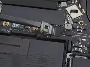
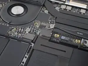
Carefully remove the metal shield.
-
The second cable you will disconnect will be lightly adhered so carefully slide a plastic spudger under it and finally unplug it.
-
-
-
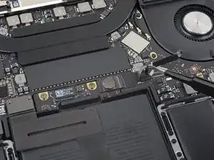
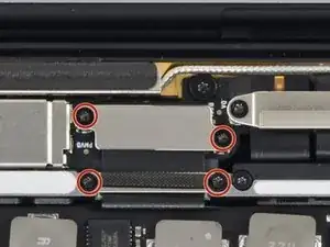
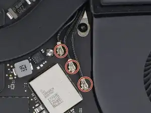
Use a T3 Torx driver to remove the four screws.
-
4 T3 Torx screws.
-
Once the screws are removed carefully remove the metal shields.
-
Carefully unclip the connector.
-
-
-
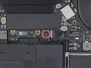
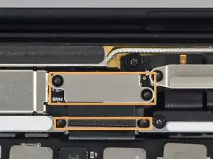
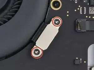
Use a T3 Torx driver to remove the two screws.
-
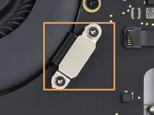
Remove the metal shield carefully.
-
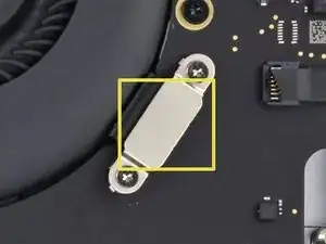
Carefully unplug the connector.
-
-
-
Carefully peel back the black tape to reveal the ZIF connector.
-
Unlatch the ZIF connector by flicking the arm on the connector upwards and carefully remove the cable from the connector by sliding it out.
-
Repeat this process with the newly revealed connector.
-
-
-
Carefully peel back the black tape to reveal the ZIF connector.
-
Unlatch the ZIF connector by flicking the arm on the connector upwards and carefully remove the cable from the connector by sliding it out.
-
-
-
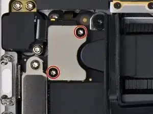
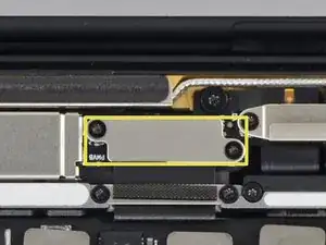
Use a T3 Torx driver to remove the two screws.
-
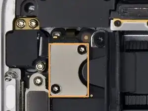
Once the screw have been removed carefully remove the metal shield.
-
Under the metal shield there is a connector, carefully unplug it.
-
-
-
Use a T4 Torx driver to remove the screw.
-
T4 Torx screw.
-
Remove the metal shield carefully.
-
Carefully unplug the connector.
-
-
-
gently disconnect the audio socket flex cable with a spudger.
-
gently disconnect the Touch ID flex cable with a spudger.
-
-
-
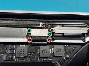
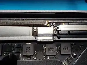
Use a T3 Torx driver to remove the two 2.4mm screws securing the display cable bracket.
-
Use a T3 Torx driver to remove the two 1.2mm screws securing the display cable bracket.
-
-
-
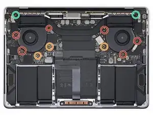
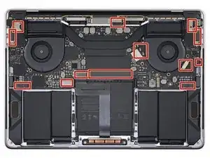
Use a T5 Torx driver to remove the six 2.2mm screws securing the logic board.
-
Use a T3 Torx driver to remove the three 1.9mm screws securing the logic board.
-
Use a T5 Torx driver to remove the two 2.3mm (3.7mm head) screws securing the heatsink.
-

To reassemble your device, follow these instructions in reverse order.

6 comments
Hi!
If anyone needs any help just ask me:-)
Thanks:-)
Bonjour, une fois la carte mère remplacer, comment remettre le nouveau numéro de série et bios à jour svp?
thu huc -
Salut, désolé pour mon mauvais français car j'utilise un traducteur pour cela :-) lorsque vous remplacez la carte logique/carte mère, la nouvelle carte aura son propre bios et son numéro de série, si vous voulez mettre à jour votre bios, il vous suffit de mettre à jour macOS
At what point would you say you need thermal paste?
You need to replace thermal past every 4years or so…or at least that’s what I do to keep the machine running cool:-)