Introduction

Prereq only.

  1. EQmXblHhw1TUufqA
    EQmXblHhw1TUufqA
    YiB11MwiLVvZYQxu
    sn1ROUjVLwDdUU1y
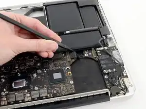
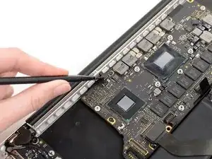
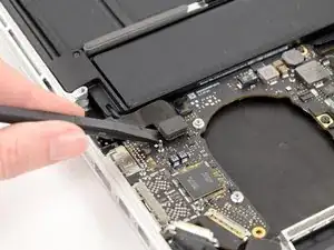
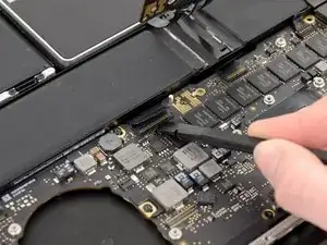
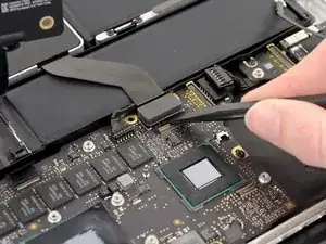
    • Use the tip of a spudger to push the edges of the I/O board connector straight out of its socket on the logic board.

    • It is recommended to carefully push on both sides of the connector to "walk" it out of its socket.

  2. rQInTMxq1qEUoBWJ
    rQInTMxq1qEUoBWJ
    eUcKbJPENu5CJoYd
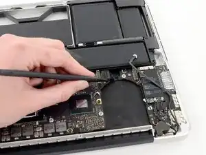
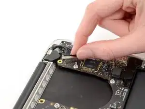
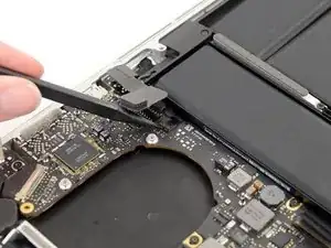
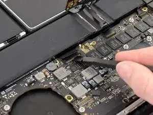
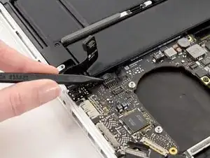
    • Wedge the flat end of a spudger underneath the keyboard backlight connector and the logic board.

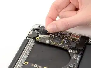
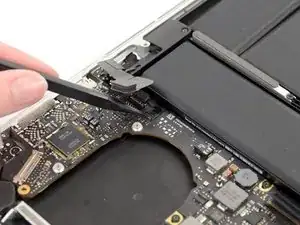
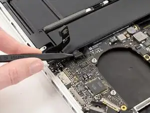
    • Gently twist the flat end of a spudger upwards to pry the keyboard backlight connector up off its socket on the logic board.

  3. yaXiQ1MF3ZDu64Kw
    yaXiQ1MF3ZDu64Kw
    sDSnXKwPOYyW54cY
    NjL2VdUbANWOoPRS
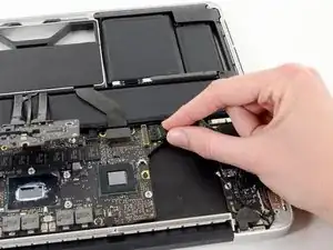
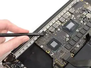
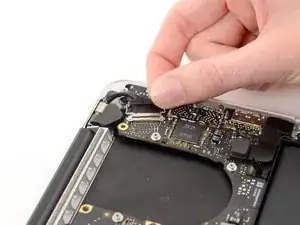
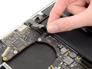
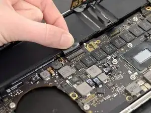
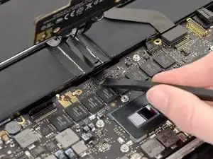
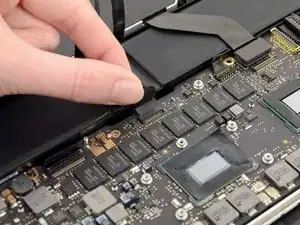
    • Grab the black pull tab secured to the display data cable lock and rotate it toward the DC-In side of the computer.

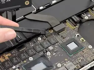
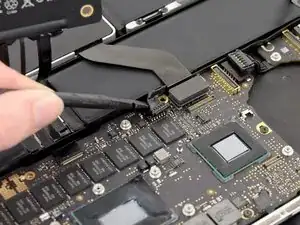
    • Pull the display data cable straight out of its socket on the logic board.

    • Do not lift up on the display data cable, as its socket is very fragile. Pull the cable parallel to the face of the logic board.

  4. 1AMyiInemOj2n6fm
    • Pry the headphone jack cable connector up off its socket on the logic board.

  5. sJQ2dtHSSfjJwdnr
    sJQ2dtHSSfjJwdnr
    2bebl5tTTiRttdHA
    OhrGfnQQyN6UWYJg
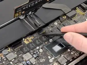
    • Use the tip of a spudger to flip up the retaining flap on the microphone ribbon cable ZIF socket.

    • Be sure you are prying up on the hinged retaining flap, not the socket itself.

    • Grasp the plastic pull tab and pull the microphone ribbon cable out of its socket.

  6. WFDhULfDIIlAYewP
    WFDhULfDIIlAYewP
    X3xxyDRnOWiwiEln
    TdBdVHUirpAFWrbo
    • Use the flat edge of a spudger to flip up the retaining flap on the keyboard ribbon cable ZIF socket.

    • Be sure you are prying up on the hinged retaining flap, not the socket itself.

    • Grasp the plastic pull tab and pull the keyboard ribbon cable out of its socket.

  7. tOlCBue6bP4ML3bS
    tOlCBue6bP4ML3bS
    nN1CJ1kcTAylHwMT
    IGRPDpmLNHFRd2Br
    • Repeat the previous procedure to disconnect the Trackpad ribbon cable from its socket on the logic board.

    I discovered that if the trackpad cable is damaged the keyboard will not work. I replaced the trackpad cable which had two damaged Ribbon pens. Once TP cable was replaced the keyboard also worked!

    Macrepair SF -

  8. qMo2HZrK2N4GoGBe
    qMo2HZrK2N4GoGBe
    4yHsrLdLGFFPED6U
    • Wedge the flat end of a spudger beneath the right speaker cable connector.

    • Gently pry the right speaker cable connector up off from its socket on the logic board.

    • Be sure you are prying up on the connector, not the socket itself.

  9. rFQrVvCulBYuELll
    • Use the flat end of a spudger to pry the SSD cable connector up off its socket on the logic board.

  10. o3hgCmTuOBSeL1ZA
    o3hgCmTuOBSeL1ZA
    bBilt5bFDmdZPZe4
    • Wedge the tip of a spudger beneath the left speaker cable connector.

    • Gently pry the left speaker cable connector up off from its socket on the logic board.

    • Be sure you are prying up on the connector, not the socket itself.

  11. VW51MEdQoVXHySqY
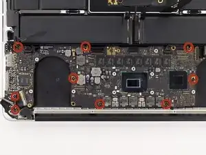
    • Remove the nine 3.3 mm T5 Torx screws securing the logic board and MagSafe DC-in board to the upper case.

  12. KthIM4TPy4oWCYAD
    KthIM4TPy4oWCYAD
    ZvDJ1Nuua3rvMYer
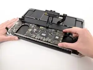
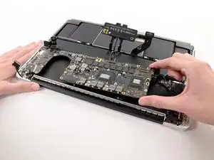
    • Carefully grasp the corner of the logic board (opposite of the I/O ports) and lift the logic board out of the upper case.

    When re-installing the Logic board, be careful not to trap any of ZIF cables under the board.

    You’ll need to tilt the board up from the end away from the DC-IN board in order to get the IO connectors inserted all the way. Be careful with the little fingers on top of the IO connectors.

    I had previously replaced the battery with the Newer Tech battery. The battery cable is not as flexible as the original battery, making the removal and insertion of the trackpad cable difficult.

    Jay Seaman -

Conclusion

To reassemble your device, follow these instructions in reverse order.

Andrew Optimus Goldheart

Member since: 17/10/09

502341 Reputation

0 comments