Introduction

Use this guide to replace the I/O board.

  1. XxSVygoKg3BQZUeK
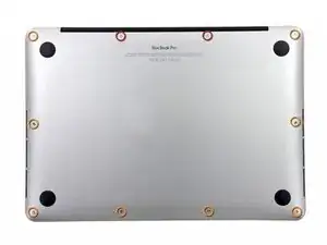
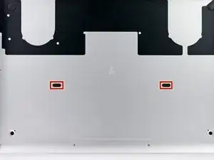
    • Remove the following ten screws securing the lower case to the upper case:

    • Two 2.3 mm P5 Pentalobe screws

    • Eight 3.0 mm P5 Pentalobe screws

    • Throughout this repair, keep track of each screw and make sure it goes back exactly where it came from to avoid damaging your device.

    If don’t have one of those neat project mats, then you can use small pieces of flattened blu-tack to hold the screws. If you arrange them in the shape of your mac book cover, and put the screws down methodically, you can get a one-to-one mapping of the screws to the correct screw holes.

    Toby Thurston -

    Or you can use an ice tray where you put the screws and the parts in separate bays in the same order as they come in the instructions.

    timofej.se -

    This is great! I used a small magnetic white board, and wrote on it to identify the parts as I went. This whole process, from the fast shipment to the great instructions to the complete, high quality, tool kit has been great. I’m typing this comment on my resurrected laptop. Thank you! Sue

    Susan Greer -

    It would be a good idea if people recorded in the comments which screws go where so that, if someone lost their screw positions, they could recover them from the comments.

    Raymond Shpeley -

  2. TZjAGsfhlId3q36t
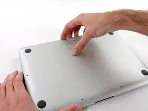
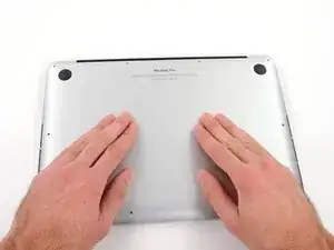
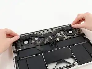
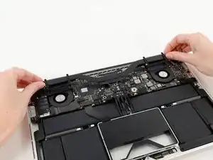
    • Wedge your fingers between the upper case and the lower case.

    • Gently pull the lower case away from the upper case.

    • Remove the lower case and set it aside.

  3. SLwb4KCgFZKfLR2B
    SLwb4KCgFZKfLR2B
    3eGiEP35uex15jKd
    muPIBpQokGnUUXJP
    • During reassembly, gently push down the center of the lower case to reattach the two plastic clips.

    • The lower case is connected to the upper case at the center, with two plastic clips.

  4. oh6QmDClHy3Es55f
    • Remove the plastic cover adhered to the battery contact board.

    The replacement cover doesn't seem to have the formed pads attached. I re-installed the original.

    Adrien -

  5. AvPUsRLbmXLZWSlb
    • Remove the following screws securing the battery connector board to the logic board:

    • Two 2.8 mm T6 Torx screws

    • One 7.0 mm T6 Torx shouldered screw

  6. eYeaxKQXRIv43WNX
    eYeaxKQXRIv43WNX
    INge1d6OYG2XdrMr
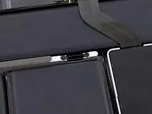
    • Use tweezers to remove the small plastic cover located near the bottom right of the battery connector board.

    Is adhered to screw beneath, so lift firmly and slowly.

    Andrew -

    when doing this with metal tweezers as instructed in the video, it was difficult to get off and apparently while i was trying to do it, the tweezers went too far under and i believe made contact with the screw underneath? there was a zzz noise, an orange flicker and a little stream of smoke that came out. i freaked out and put everything back together to see if the laptop even still worked, it turned on and everything but died right away (i drained it before doing the repair anyway, so i was surprised it turned on at all).

    i finished the battery repair and did several other things while in there. i have charged it all the way as recommended and will use it later on to see how everything is, im hoping that it’s a okay, but could someone explain to me what happened and the possible consequences?

    Kait D -

  7. 3h3p5bF5gSsxU3H1
    • Remove the wide head 6.4 mm T6 Torx screw securing the battery connector to the logic board assembly.

    When reinstalling, be careful that the board lines up correctly and is completely seated in order for this screw to thread properly.

    Adrien -

  8. KnflDJ6YcW61sb3S
    KnflDJ6YcW61sb3S
    Y3LPyukbnPaH2Qua
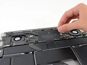
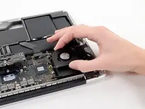
    • Carefully lift the battery connector board up off the logic board.

    • It is recommended to bend the battery cables just slightly, to keep the board suspended up above the logic board and out of the way.

    • Do not fold the board completely over, or crease the cables, as this may damage the battery.

  9. wBB3HYE4h4RPE1gv
    wBB3HYE4h4RPE1gv
    oUwSuUJp4RWM4RSK
    • Grasp the Interposer with tweezers.

    • An interposer is the name for an interface that links one electrical connection to another. In this repair, it is the board connecting the battery to logic board.

    • Lift the Interposer off the logic board and remove it.

    • Removing this board will ensure that the battery remains disconnected throughout your repair, preventing your computer from accidentally powering on. It's also a good idea to take it out so it doesn't fall out unexpectedly.

    How can I remove interposer I m not able to remove it

    Raunak -

    you must lift it absolutely vertically, or it fouls against the locator pin in the corner- you can easily get the impression that it won’t come over the end of this pin- almost like it’s rivetted in. it isn’t. get a good grip on it with the tweezers in the centre hole & one of the sides, & lift it STRAIGHT up.

    duncan rmi -

    I would recommend to use plastic tweezers in order to reduce risk of damage.

    Martin Sippel -

    Second that. If you have thin heat shrink tubing, form some over the tweezer tips. If the tubing is thin and small enough in diameter you’ll see the serrations of the tweezer tips.

    Raymond Shpeley -

    wat is the model this SSD

    thierry.wilow -

  10. udxaOR4MFVLGCxKC
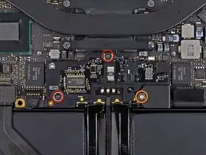
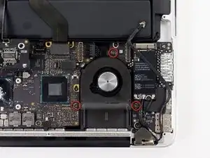
    • Remove the following screws securing the heat sink to the logic board assembly:

    • One 2.4 mm Phillips #00 screw

    • One 3.4 mm T5 Torx screw

    • Four 2.7 mm T5 Torx screws

    Hi,

    found 4 rubber spacers on the 4 2,5mm screws

    ddagonetroppo -

    Also found the rubber caps on the 4x2.7mm - didn't bother to replace the caps and didn't have any problems with them.

    Rand Bell -

  11. CWCPSycgexGQB2r3
    CWCPSycgexGQB2r3
    TvEGfitWVUgpJy6c
    • Lift and remove the heat sink up off the logic board assembly.

    • When reinstalling the heat sink, be sure to apply a new layer of thermal paste. If you have never applied thermal paste before, we have a guide that makes it easy.

  12. Qhauofpvg6McR5GQ
    Qhauofpvg6McR5GQ
    pSlBL1Mu5kLDXoSa
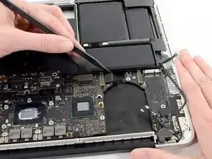
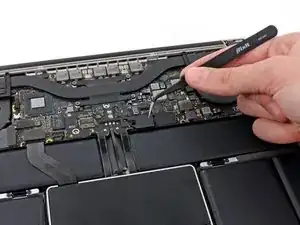
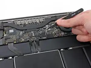
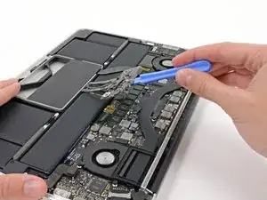
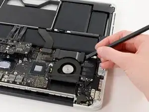
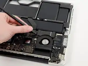
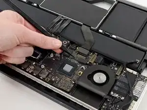
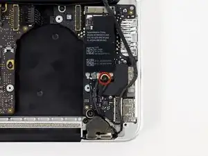
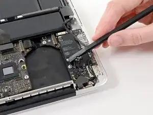
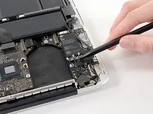
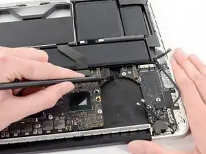
    • Use the flat end of a spudger to pry the right side of the I/O board data cable connector up off its socket on the I/O board.

    • When prying the I/O board data cable connector from its socket, make sure to pry the connector itself and not the socket. Prying the socket may cause irreversible damage to the I/O board.

  13. OvJFKtFYMRoCSRaB
    OvJFKtFYMRoCSRaB
    FS2OoLlUaNCRbDjO
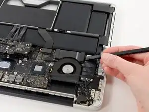
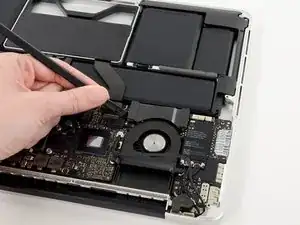
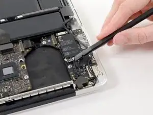
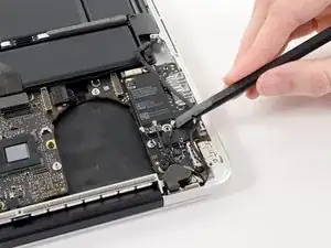
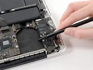
    • Wedge the flat end of a spudger beneath the left side of the I/O board data cable connector.

    • Gently twist the spudger to disconnect the I/O board data cable connector from its socket on the logic board.

  14. pwNcLhGv3LkbAeUv
    • Lift and remove the I/O board data cable from the MacBook Pro.

  15. aJbomd42BiEmjgGH
    aJbomd42BiEmjgGH
    F4kLaJHGIOL15Js2
    bODTNv1HeDLEOEfl
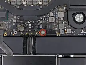
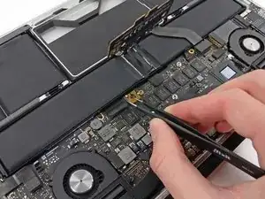
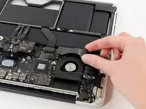
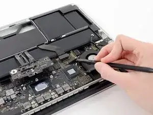
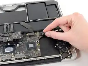
    • Use the tip of a spudger to flip up the retaining flap on the right fan ribbon cable ZIF socket.

    • Be sure you are prying up on the hinged retaining flap, not the socket itself.

    • Pull the right fan ribbon cable straight out of its socket on the logic board.

    Hey! You skipped a step!

    What about the cable (don't know what it does) that runs right across the fan, interfering with pulling the fan out.

    It's still in place in Step 14, but here in Step 15 it's magically removed itself, and can be seen resting luxuriously on top of the Airport card.

    How do we get that outta there?

    Victor Gavenda -

    Like @victorgav mention, Just need a step before this one, which is to remove the cable that goes across the top of the fan.

    David Borjas -

    Thanks for bringing this up! It looks like the guide was missing the iSight cable disconnection steps. I’ve added the missing steps.

    Arthur Shi -

    This cable simply plugs into its silver connection housing. So to remove simply wiggle it out gently with a pair of tweezers

    Wasim -

  16. EPKxa3xZqdgPp3IN
    • Remove the three 3.1 mm T5 Torx screws securing the right fan to the logic board assembly.

  17. tJ1NPgQjsVKjKgRy
    • Lift and remove the right fan out of the upper case.

  18. ZFA4JklFPsGbEUbw
    • Remove the single 2.7 mm T5 Torx screw securing the AirPort board to the I/O board.

  19. AksHUHLaCt3YnQcg
    AksHUHLaCt3YnQcg
    piwekcwhNDtWbY6C
    Oaud1utQqAtFRAQa
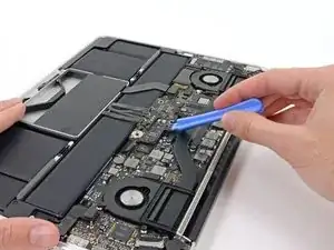
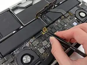
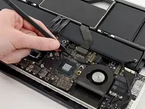
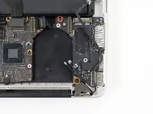
    • Use the flat end of a spudger to pry and disconnect the three antenna cable connectors from the AirPort board.

    • The three cables are coded with black sleeves of different lengths. During reassembly:

    • Connect the long-sleeved cable to the center socket.

    • The short-sleeved cable connects next to the screw.

    • The remaining cable has no sleeve, and connects in the last empty socket, next to the fan.

  20. 4lsiIG3xLaWceBBP
    4lsiIG3xLaWceBBP
    io6ckDGKBW2Hk16u
    • Move the antenna cables aside, clear of the AirPort board.

  21. eSWyoOE2U6ESxAFb
    eSWyoOE2U6ESxAFb
    cCigkp2CvVvEKipR
    • Pull the AirPort board straight out of its socket on the I/O board.

  22. 2ZSKcfc2ZjBUFpUT
    2ZSKcfc2ZjBUFpUT
    HyeF1qKGQ3fNZqJc
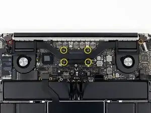
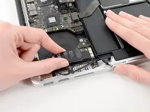
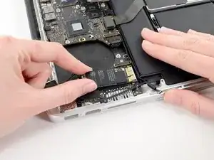
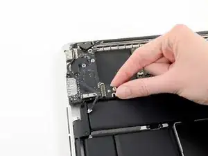
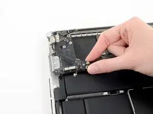
    • Use the tip of a spudger to push the edges of the I/O board power connector straight out of its socket on the logic board.

    • It is recommended to carefully push on both sides of the connector to "walk" it out of its socket.

  23. PJ2Opt4gIvLOFGNj
    • Pull the I/O board connector straight out of its socket on the logic board.

  24. xnfjA5NHcaQgHsOB
    • Remove the following two screws securing the I/O board to the upper case:

    • One 3.5 mm T5 Torx screw

    • One 4.9 mm T8 Torx screw

  25. l5jxdQutkSc5xsVJ
    l5jxdQutkSc5xsVJ
    bMIVQQoSeaNn6fnf
    • Carefully pull and remove the I/O board away from its recess in the upper case.

Conclusion

To reassemble your device, follow these instructions in reverse order.

Walter Galan

694047 Reputation

0 comments