
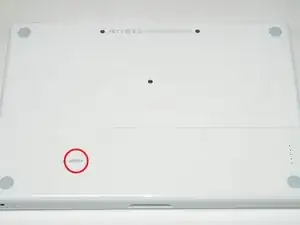
Introduction
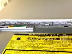
The heat sink helps keep the processor cool and happy.
-
-
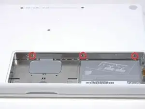
Unscrew the three evenly-spaced Phillips screws from along the rear wall of the battery compartment.
-
-
-
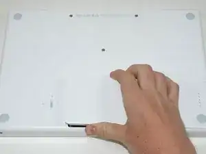
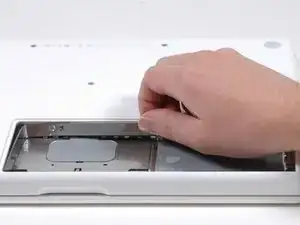
Grasp the right end of the L-shaped memory cover, then pull it towards you so it clears the battery compartment opening.
-
Lift the memory cover up and out of the computer.
-
-
-
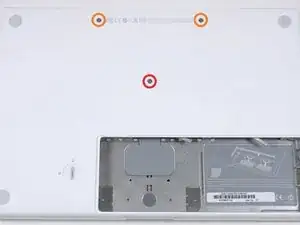
Remove the following 3 screws:
-
One 11 mm Phillips#00 in the middle of the lower case. (Head: 5mm dia. x .75mm thick)
-
Two 14.5 mm Phillips #00 (Head: 5mm dia. x .75mm thick)
-
-
-
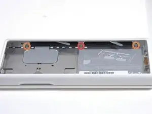
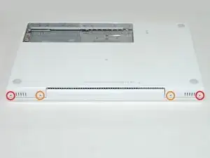
Remove the following 3 screws from the rear wall of the battery compartment:
-
One 3 mm Phillips #0. (Head: 2.75 mm. dia.)
-
Two 4 mm Phillips #0 on the either side. (Head: 2.75mm dia.)
-
-
-
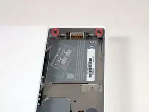
Remove the two Phillips screws from either side of the right wall of the battery compartment (not the ones closest to the battery connector).
-
Two 6.25 mm Phillips #000. (Head: 4 mm. dia. x .5mm thick)
-
-
-
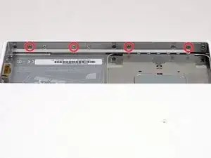
Remove the four indicated Phillips screws from the front wall of the battery compartment. When working from the left, remove the 2nd, 4th, 7th and 9th screws.
-
Four 3.25 mm Phillips #000. (Head: 4 mm. dia. x 4mm thick)
-
-
-
Remove the following 4 screws from the back of the computer:
-
Two 11 mm Phillips #00, with Shank (2.2mm dia. x 2 mm len.) (Head: 3.2 mm. dia. x .5mm thick)
-
Two 7.25 mm Phillips #00, with Shank (2mm dia. x 3.75 mm len.) (Head: 3.2 mm. dia. x .5mm thick)
-
-
-
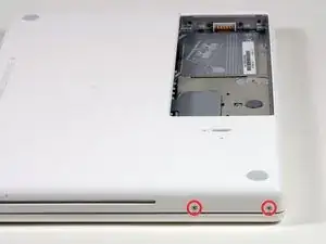
Remove the two Phillips screws from the optical drive (right) side of the computer:
-
Two 5.2 mm Phillips #00, with shank (2.3mm dia. x 3.25 mm len.) (Head: 3.2 mm. dia. x .5mm thick)
-
-
-
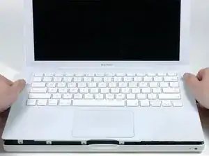
Use a plastic opening tool, an expired plastic credit, or a similarly-thick card to pry up on the upper case, starting in the upper-left corner and working around to the front of the computer.
-
-
-
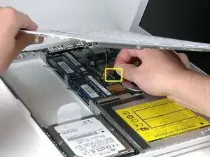
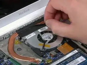
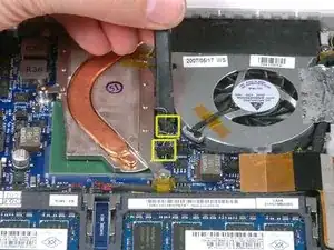
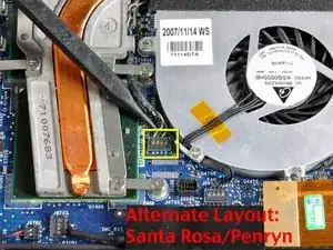
While holding up the upper case, pull up the black tab on the connector end of the silver ribbon cable away from the connector's socket on the logic board.
-
-
-
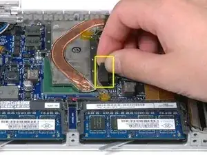
Use a spudger to disconnect the two newly-revealed temperature sensor connectors from the logic board.
-
-
-
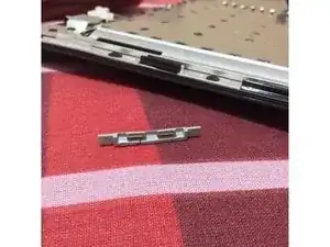
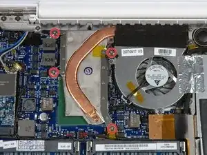
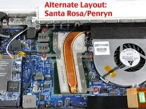
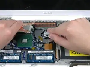
Lift the heat sink out of the computer, making sure the black tape doesn't catch on the heat sink.
-
To reassemble your device, follow these instructions in reverse order.

7 comments
what if the black felt tape is dissolve itself in step 13? do i have to renew it or doesnt metter? it just crumbled.
Hi.
I love these guides, they have helped me to replace the airport card, replace the keyboard cable and modify the optibay to install a 2nd drive.
The last 2 jobs I have completed were to remove the cooling fan to clean it and the exit of the heat sink and later to remove the heat sink to renew the thermal paste conducting material.
My suggestions would be if you are going to remove the heat sink take out the cooling fan first. This is just because the removal of the heat sink is much easier if the fan is out and it's really not too much more work and when you re-assemble make sure the black tape is really sticking down, if it's not the full cooling will be lost and funnily enough the noise of the fan increases.
Thanks ifixit team, you have been life savers.
respect
I used the guide and had no problems getting to the point of replacing the heatsink. I see how the rear heat sensor (250) clips onto the logic board but for the life of me, I cannot see how the longer sensor attaches. I see two contacts but other than the felt thing, there is no way to attach. . . What did I do wrong. . . HELP. Milt King
I used this guide plus the Thermal Paste guide to resolve my MacBook RRS (Random Restart Syndrome) issue. My MacBook would randomly restart after the fan kicked into high speed. When I removed the heatsink I discovered an an irregular patch completely free of thermal compound of about 15-20% of the area on one of the processors. I removed and re-applied the thermal paste. I ran a memory test utility overnight that previously caused a restart after a couple of hours, and the probelm seems to be solved. TIme will tell.
ServiceDocs -