Introduction
Replace the optical drive cable if the connector is broken or the ribbon cable itself is damaged.
-
-
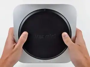
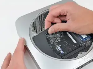
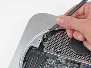
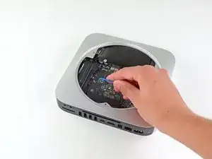
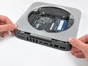
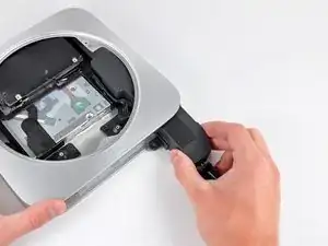
Place your thumbs in the depressions cut into the bottom cover.
-
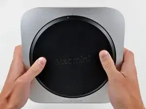
Rotate the bottom cover counter-clockwise until the white dot painted on the bottom cover is aligned with the ring inscribed on the outer case.
-
-
-
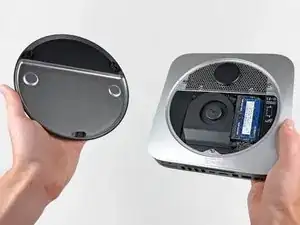
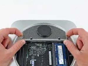
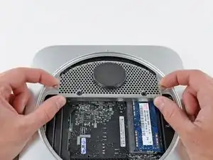
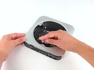
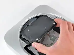
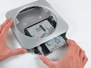
Tilt the mini enough to allow the bottom cover to fall away from the outer case.
-
Remove the bottom cover and set it aside.
-
-
-
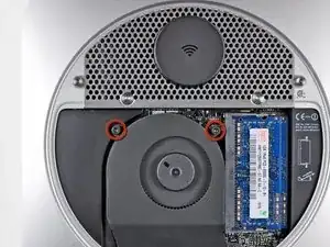
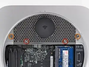
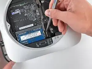
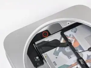
Remove the two 11.3 mm T6 Torx screws securing the fan to the logic board near the antenna plate.
-
-
-
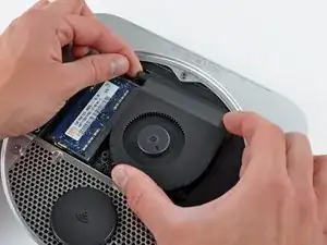
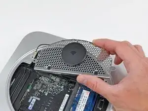
Lift the fan out of the mini for enough clearance to access its connector.
-
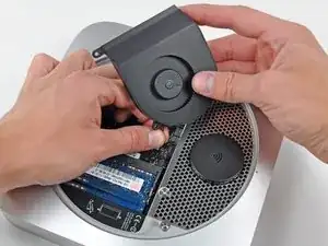
Carefully pull the fan cables upward to lift the fan connector up out of its socket on the logic board.
-
Remove the fan.
-
-
-
Lift the cowling from the end nearest the antenna plate.
-
Rotate the cowling away from the outer case and remove it from the mini.
-
-
-
Remove the following screws securing the antenna plate to the mini:
-
Two 6.6 mm T8 or T9 Torx screws
-
Two 5.0 mm T8 Torx or 2.0 mm Hex screws (either will work)
-
-
-
Slightly lift the antenna plate from the end closest to the RAM.
-
Carefully pull the antenna plate straight away from the circular rim of the outer case.
-
-
-
Use the tip of a spudger to carefully pry the antenna connector up off the AirPort/Bluetooth board.
-
-
-
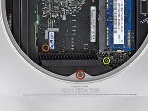
Remove the following three screws:
-
One 5.0 mm T8 Torx or 2.0 mm Hex screw (either will work)
-
One 16.2 mm T6 Torx screw
-
One 26 mm T6 Torx standoff
-
-
-
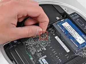
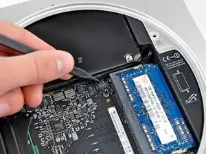
Carefully pull the wires for both hard drive thermal sensors upward to lift their connectors up and out of the sockets on the logic board.
-
-
-
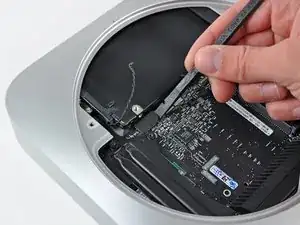
Use the flat end of a spudger to pry both the hard drive and optical drive connectors up out of their sockets on the logic board.
-
-
-
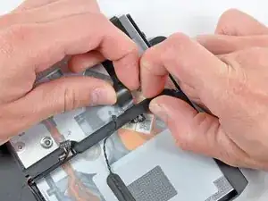
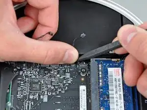
To disconnect the optical drive thermal sensor, pinch its cables between your thumb and a spudger and pry the spudger upward to lift the connector up and out of its socket on the logic board.
-
-
-
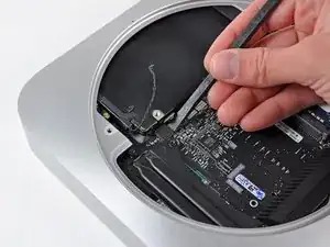
Use the tip of a spudger to lift the IR sensor connector up and out of its socket on the logic board.
-
-
-
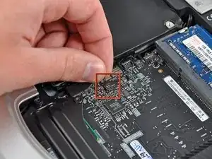
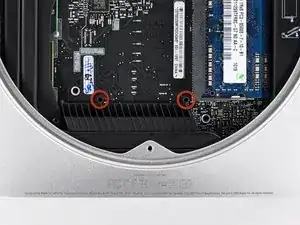
Insert a Mac mini Logic Board Removal Tool into the two holes highlighted in red. Be sure it makes contact with the outer case below the logic board before proceeding.
-
Carefully pull the tool toward the I/O board. The logic board and I/O board assembly should slightly slide out of the outer case.
-
Cease prying when the I/O board is visibly separated from the outer case. Remove the Mac mini Logic Board Removal tool.
-
-
-
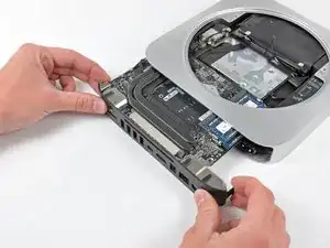
Simultaneously push the two plastic clips on the far left and right sides of the I/O board toward the middle of the I/O board and pull the I/O board away from the outer case.
-
-
-
Pull the I/O board/logic board assembly out of the outer case enough to access the power connector.
-
Use a pair of tweezers to disconnect the power cable from the logic board.
-
-
-
Carefully slide the logic board assembly out of the mini, minding any cables that may get caught.
-
-
-
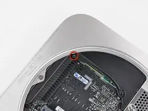
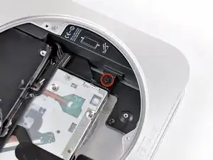
Remove the 7.9 mm T6 Torx screw securing the power supply and optical drive to the outer case.
-
-
-
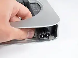
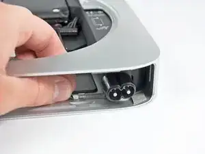
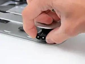
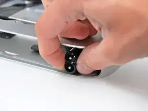
Pull the silver metal AC-In socket retainer away from the side of the outer case and remove it from the mini.
-
-
-
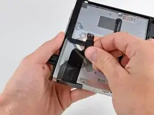
Slightly lift the small plastic strip spanning the width of the optical drive.
-
Carefully de-route the free end of the optical drive connector out from under the optical drive bracket.
-
-
-
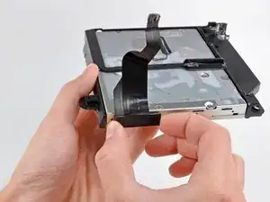
Remove the optical drive cable by pulling its connector away from the body of the optical drive.
-
To reassemble your device, follow these instructions in reverse order.

There are actually 3 T6 screws securing the fan. The third screw is out of the screenshot, just below the RAM.
inferno10 -
Nope, that third screw is actually just a post that the rubber grommet attached to the fan body slips over. Step 4 shows how the fan comes off of it. When you go to remove the fan, you simply remove the two screws closest to the antenna plate and then lift the fan off this post. The screw you are talking about is removed in Step 14 and does not need to be removed until this point.
Andrew Bookholt -
Successful install completed, but I had some trouble getting the fan reinstalled. When I removed the fan from the "Step 14" post, the rubber piece stayed on the post. When attempting to reinstall the fan, it was impossible to get the loop to go back over that rubber piece. So, I had to remove the post (again), and with the help of the spudger and some patience, worked it through. Then installed the fan using the 2 screws and the post. I think it may have saved some time and trouble if I just removed all 3 in the first place, leaving the post in the fan.
meag -
On mine I needed to remove the 26 mm T6 Torx standoff during this step rather than step 12
philipashlock -
on my mid-2011 mac mini, that 3rd T6 post/screw had to be removed to get the fan out. It goes right through a hole in the fan housing. No way the grommet is slipping over anything without wreaking major havoc.
Derek Shaw -
On my mid-2010 mac mini, also removed the 26 mm T6 Torx standoff during this step instead of step 12. Having completed the steps, it appears my hard drive is from mid 2011, so maybe the production line for mine had changed.
jstraath -