Introduction

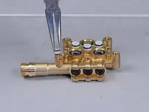
Follow this guide to rebuild the pump for the Karcher 15209900 electric pressure washer.

In order to complete this, you will need the pump rebuild kit. All of the parts that are replaced in this rebuild are listed in the guide.

Some of the body screws are deeply recessed and require a T15 driver with a 5-inch long shaft in order to reach.

Part of this procedure requires removing the pump assembly, with is partially filled with oil. You must refill the oil during reassembly. The part number for the oil is 6.288-219.0.

  1. sTyv3aNB2dm4MfO2
    sTyv3aNB2dm4MfO2
    D5ZbsGfh5ZyvgrQ5
    cgc3nZYGHJLUxwK4
    • Before you begin, make sure to power off and unplug the device from the outlet.

    • Unscrew the output hose from the pressure washer.

  2. EBWTJQJvxAIWl2RR
    EBWTJQJvxAIWl2RR
    MHUOdQnUBNgZby1Y
    JJQHjA11NFPhgEhS
    • Unlatch and remove the yellow rubber strap.

  3. WZIEbM5oYdcE2Nr4
    • Use a T20 driver to remove the two 55mm-long screws securing the hand grip.

  4. KieVyE5DudJoAPJB
    KieVyE5DudJoAPJB
    epyU11vLeXSbBtaX
    • Remove the hand grip from the extension bars.

  5. GejtniRRWSLli5wc
    GejtniRRWSLli5wc
    Rgavs3HXQyLABqEX
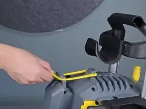
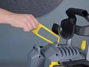
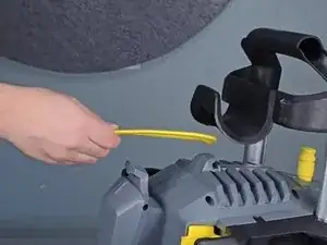
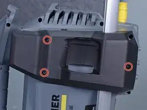
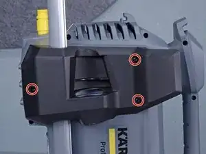
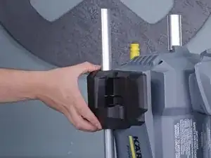
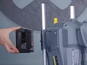
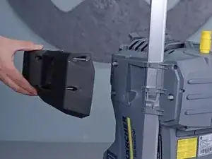
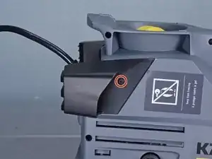
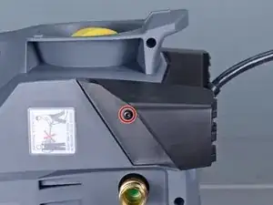
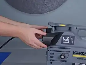
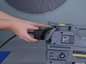
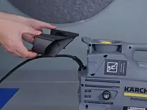
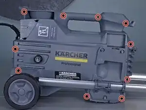
    • Use a T15 driver to remove the six screws securing the top black plastic panels on either side of the device.

  6. Z21nN4HX5GBuiWlc
    Z21nN4HX5GBuiWlc
    CnQr3PdIFhcvZPQc
    YL4amS16wgUWGNVj
    • Remove the two plastic panels.

  7. 4XhUxZhSrZW4HDY4
    4XhUxZhSrZW4HDY4
    uRIaK6tDrcQHtfJb
    • Remove the two T15 screws securing the plastic feet—one screw on either side.

  8. 1OMyUwN3wEnJ3qft
    1OMyUwN3wEnJ3qft
    VJA2KqOF1vRnenSZ
    o66w1MC2IXZO5qoX
    • Unclip and remove the plastic feet.

  9. fkyCtREJdmWQW4gT
    fkyCtREJdmWQW4gT
    bnjfYkiAyFPbUefQ
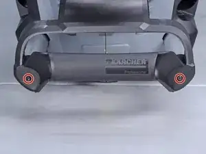
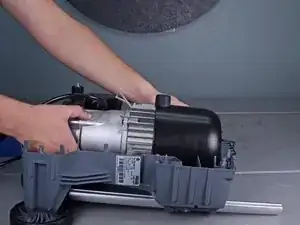
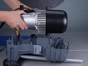
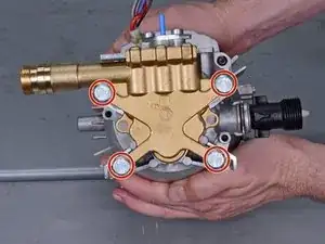
    • Use a T15 driver to remove the ten screws securing the housing halves together.

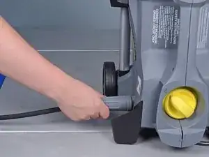
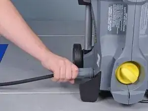
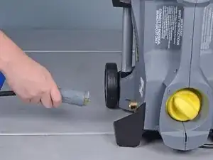
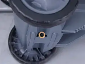
    • Remove the T15 screw underneath the wheel axle.

  10. LGcMqoMCNRqw6Oex
    LGcMqoMCNRqw6Oex
    GRfIFvXqEympLqSO
    • Set the device on its side.

    • Lift the housing half away from the body.

    • If the housing half does not separate, check to make sure you removed all the body screws.

    • Remove the housing.

    • Screws may get stuck inside the plastic housing. Be careful not to lose any screws.

  11. ZwTrKUJiLJvBQjVi
    ZwTrKUJiLJvBQjVi
    kRVq2dtRgsuncNGm
    • Slide the power cord strain relief out its notch on the plastic housing.

  12. XEUfShGY45o5ephH
    XEUfShGY45o5ephH
    5RsBLcA2PuuPlLhm
    • Lift the motor assembly out of the plastic housing and set it aside.

  13. 4KrlWNS4rVPZvNNl
    4KrlWNS4rVPZvNNl
    gPTwA5x1aENRxsPp
    Ab2xCsdeEBTakaAP
    • Reassembly tip: Use these images to help reassemble the housing back around the motor.

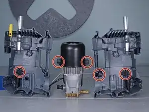
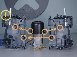
    • Make sure that all five bushings are in place.

    • In order for the housing to fit properly, the bushings must fit in their respective mounts.

    • Make sure that the yellow tube is properly notched onto the housing.

    • Make sure that the power cord strain relief sits correctly in the housing notch.

  14. iogFPNpjLaD3Jmn1
    • Use a T20 driver to remove the four screws securing the electrical box cover.

  15. w4VaUn2qXJQtXhrR
    w4VaUn2qXJQtXhrR
    KjXGZng2tsCKaQEQ
    • Lift the cover off of the electrical box.

  16. gJOxM2O6jcQI2FM5
    gJOxM2O6jcQI2FM5
    BicQBGUk4CmXuIrH
    • Tilt the capacitor upward slightly to gain access to the connectors.

  17. PXygAQyQCdONyaAF
    PXygAQyQCdONyaAF
    qW1Q3JYtvOC1ySTS
    XeCCJt5XUrFTfBlA
    • Use your fingers to pull each capacitor connector directly off of their spade plug.

  18. xMr1QVPOVnLReaSF
    • Remove the capacitor.

    • Reassembly note: The wires are non-polarized and can connect into either plug on the capacitor.

  19. dAElsVu1ABAL2rUK
    dAElsVu1ABAL2rUK
    MkSQ5jDEtbISlqLh
    • Remove the plate spring from the electrical box.

    How to replace back the switch in the box?

    k27b -

  20. NsbeeXQwcWCXLrIu
    NsbeeXQwcWCXLrIu
    VbvBuICJpQYrkUOy
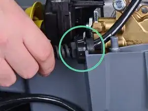
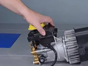
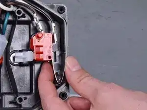
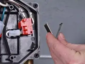
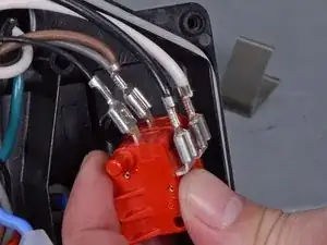
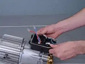
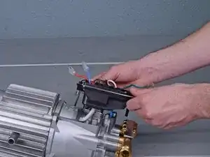
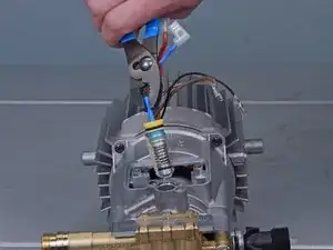
    • Pull the switch out of the electrical box.

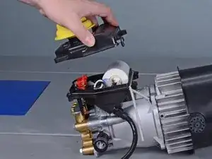
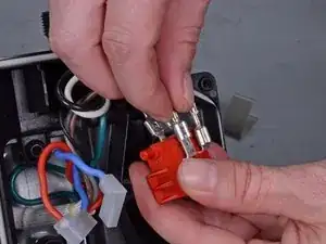
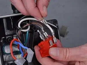
    • Disconnect the four spade connectors from the the switch.

  21. SUfl1MqKP1QnuiER
    SUfl1MqKP1QnuiER
    REFBCqLwBO6rQTOc
    • Remove the switch.

    • Reassembly tip: Use the second photo as a reference to help you properly re-wire the switch.

  22. OlWJHvuIqnsjHuuB
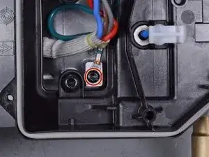
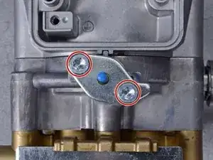
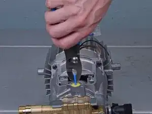
    • Use a flat head screwdriver to remove the screw securing the ground wire in the electrical box.

  23. Nr1Fo1aUtJVcOEBp
    • Use a T30 driver to remove the two bolts securing the electrical box to the motor assembly.

  24. OrgOAebZrb2qZS24
    OrgOAebZrb2qZS24
    ceRHMJQkbOaD1gLf
    S2v1IQuTSX2ODmn1
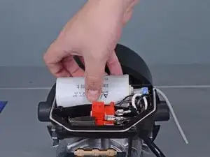
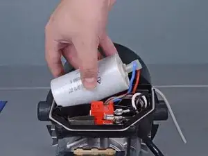
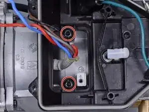
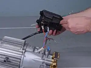
    • Lift the electrical box away from the motor assembly, taking care to feed the wires through the cutout.

    • Remove the electrical box.

  25. eFhEDhW6OZUdbQDu
    • Use a T30 driver to remove the two bolts securing the excess current cover plate.

  26. 63vfXbkRhyFApy3m
    63vfXbkRhyFApy3m
    TVduBpYICJT6fXMS
    • Remove the excess current cover plate.

  27. dfS2gc1clfVA4BCq
    dfS2gc1clfVA4BCq
    GVGCdF5n5vWF5sKD
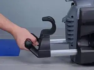
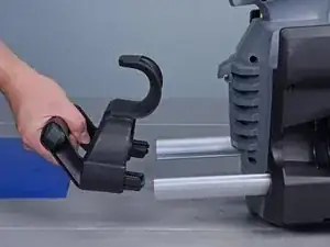
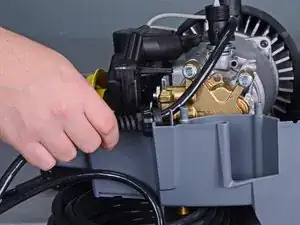
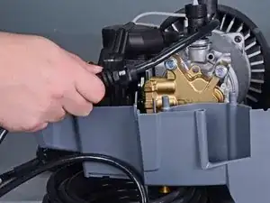
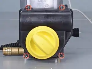
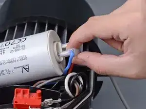
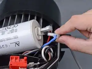
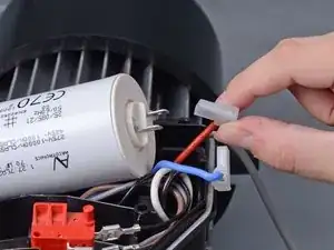
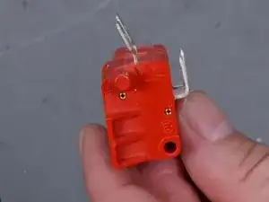
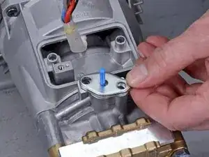
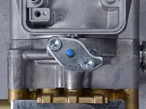
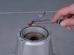
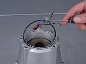
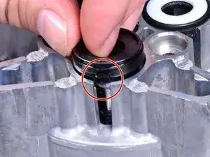
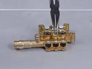
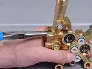
    • Use a pair of pliers to grasp the blue tab on the excess current valve.

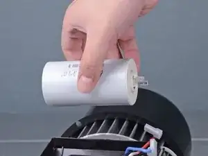
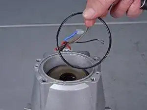
    • Pull firmly to extract the excess current valve from the pump assembly.

  28. 4WZPv1BbxYbDfYWo
    4WZPv1BbxYbDfYWo
    DrKRxxdIIBYNHTee
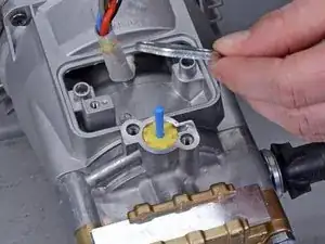
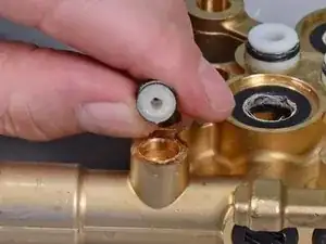
    • Lubricate the replacement valve's O-rings with the grease included in the rebuild kit.

    • Press the replacement valve back into the pump.

    • Replace the cover plate with a new one from the rebuild kit.

  29. lGEKLQHefLEqjTdL
    lGEKLQHefLEqjTdL
    qRPCeaN6afOKCbUQ
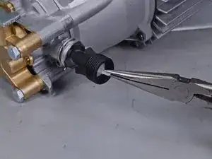
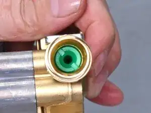
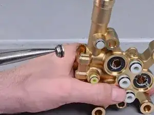
    • Use pliers to grasp the tip of the fine filter in the water intake connector.

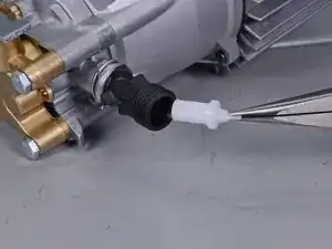
    • Pull the fine filter out of the intake.

    • Replace the fine filter with a new one from the rebuild kit.

  30. OQAaDGocrWqsVxgr
    OQAaDGocrWqsVxgr
    TFVgaNBeU5qCAuTI
    qceDBEftEQDAiysZ
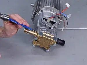
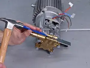
    • Use a hammer and pin punch to tap the cylinder head plate out of its groove.

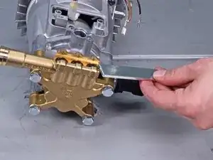
    • Remove the cylinder head plate.

  31. YKx3kd6yLlHEcyGZ
    • Set the motor assembly upright with the pump assembly on the top.

    • The pump assembly is filled with oil. This step prevents the oil from spilling out when you remove the pump.

  32. cZRdsBQUNhPdft1r
    • Use a 13mm socket to remove the four long bolts holding the pump assembly to the motor.

    • Re-assembly tip: The bolts hold the pump under pressure against the motor assembly. During reassembly, gradually tighten the bolts in a cross pattern.

  33. SFYFESjAbcUjKjJY
    SFYFESjAbcUjKjJY
    SetnLrcHEfnePoHy
    • Lift the pump assembly off of the motor.

  34. D2MVsAPBaTcqMFgT
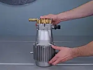
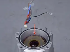
    • Pour the pump oil out of the motor housing. If the oil looks serviceable, save it for reassembly.

    • Reassembly tip: The piston assembly is sealed with oil, and the motor housing acts as an oil pan. Before you attach the pump to the motor, fill the piston well with oil, up to the bearing plate.

    what type of oil lubricant ?

    Jirawat Wattanakuljaroensin -

    What oil weight is used? Is it this 15W-40 Karcher oil?

    https://www.amazon.com/Karcher-6-288-050...

    blatch76 -

  35. ITjVYd3nBFMOQAdB
    ITjVYd3nBFMOQAdB
    dkWD4UxrvaBJA1t3
    tNqDcp2IyElTls5j
    • Remove the motor/pump O-ring from the motor assembly.

    • Replace the O-ring with a new one from the rebuild kit.

    • Be sure to lubricate the O-ring with the grease included in the rebuild kit.

  36. qkLiMp5pyXxtBYVA
    qkLiMp5pyXxtBYVA
    hg1oeMlX3vDVqCSx
    dkxuUMWwjELtKncv
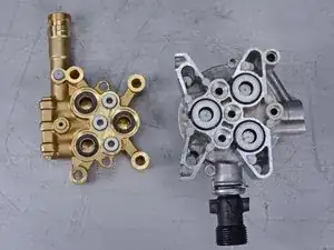
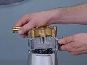
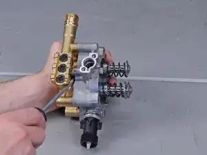
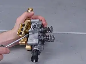
    • Use a large flat head screwdriver to loosen the cylinder head from the piston assembly.

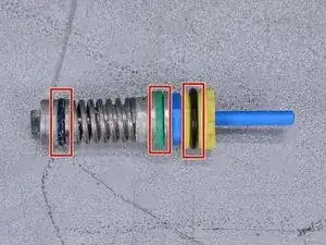
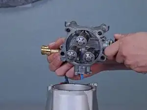
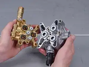
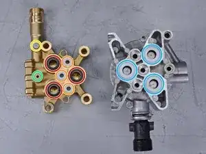
    • Pull the cylinder head and piston assembly apart.
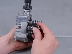
  37. nxBPHtrVkLjPYiuG
    nxBPHtrVkLjPYiuG
    2XMTpkFAIBDSS3LC
    • Remove the three pistons and pressure springs from the piston assembly.

  38. i4S4YqZOx2dGcXE4
    i4S4YqZOx2dGcXE4
    mgwDYmjGtVIaxlRs
    • Return to this step after you have finished the pump rebuild, and follow the instructions in reverse to reassemble your device.

    • Reassembly tip: Before putting the pump back together, make sure you have installed the following parts:

    • Three grooved rings

    • Three suction valves

    • One throttle piece

    • One joining piece

    • Three white washers

  39. bHa4GLlPdTKicUZM
    bHa4GLlPdTKicUZM
    3rZSGb4tdlu5pLGV
    • Use a pick tool to remove the three white washers from the piston cylinders.

  40. N3DPcGtbIyQXGPt2
    N3DPcGtbIyQXGPt2
    SIHropDBa3fAGWDY
    • Use a pick tool to remove the three black washers from the piston cylinders.

  41. drweATTG1MuiedyX
    drweATTG1MuiedyX
    JgKNgFaj23yumSML
    GyhJwLKQf6JqEykI
    • Use a screwdriver to dislodge and remove the three grooved rings from the piston cylinders.

  42. h6HtZcPn2iBxPbQi
    h6HtZcPn2iBxPbQi
    mxngPDZpiN5u6oDW
    cOjNdQoK5Qo6VfaP
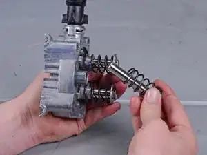
    • Replace the sets of grooved rings, black washers, and white washers with new ones from the rebuild kit.

    • Apply grease to the replacement grooved rings.

    • Note the orientation of the grooved rings when you insert them into the piston cylinder.

    • When you replace the black washers, note that they are keyed to the piston cylinders.

  43. ukBeHyQsYUD1fPcW
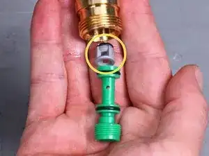
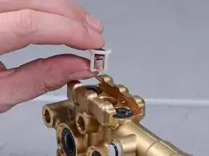
    • Use a large flat head screwdriver to unscrew the green nozzle insert from the cylinder head.

  44. dYCaVetrSE1jYWwe
    dYCaVetrSE1jYWwe
    X4tuNQLBEfuUPyBf
    • Tip the nozzle down to dump out the nozzle insert.

    • Replace the gray valve pin with a new one from the rebuild kit.

    • Screw the green nozzle insert back into the port.

  45. JvFBZuOONMO1AsMV
    JvFBZuOONMO1AsMV
    6Z4hLbkTx4pGhjQk
    e2DtpKnFYYC4tAhp
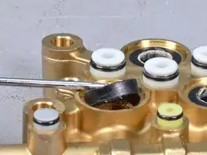
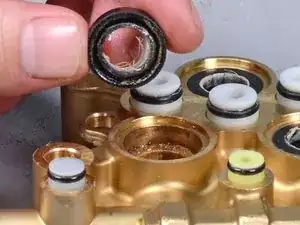
    • Remove the three black grooved rings from the cylinder head.

    • Replace the rings with new ones from the rebuild kit.

    • Reassembly tip: The groove side of the rings should sit against the cylinder head.

  46. aClMvXYSwahHRMSw
    aClMvXYSwahHRMSw
    ds2AyAGw1IjGffgp
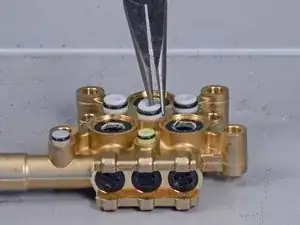
    • Use pliers to pull the three suction valves out of the cylinder head.

    • Replace the suction vales with ones ones from the rebuild kit.

  47. pgPQaywfFAcrQGkA
    pgPQaywfFAcrQGkA
    hDhrak2RYXlNji1I
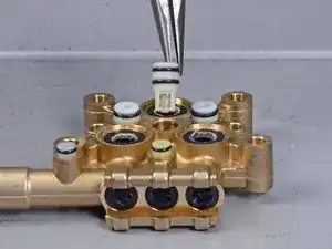
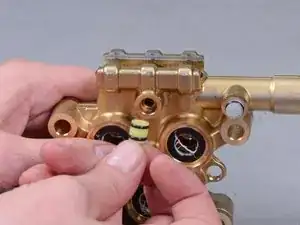
    • Use pliers to remove the throttle piece from the cylinder head.

    • Replace the throttle piece with a new one from the rebuild kit.

    • Reassembly tip: The throttle piece is directional. The end with the larger opening should face the cylinder head.

  48. SqL6oFxdAFFRHInB
    SqL6oFxdAFFRHInB
    Jx5efixRoDmJvI1N
    • Use pliers to remove the joining piece from the cylinder head.

  49. iOFlNZd1MqTLDCm5
    iOFlNZd1MqTLDCm5
    p4YdXbeCTyKUTcGF
    4olvvAcTRiIbbUXe
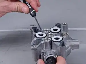
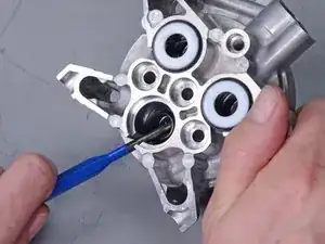
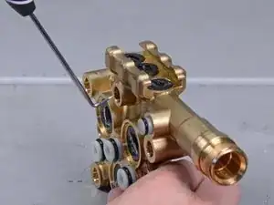
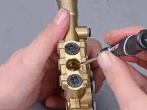
    • Insert an L-shaped pick tool into the hole that was previously covered by the joining piece.

    • Press upwards to loosen the center drain plug.

    • The drain plug is firmly held in place and may require significant force to loosen.

  50. VN1prVXCSfYyOHyC
    • Remove the center drain plug.

  51. IiBZ6CaOw4BbIqQe
    • Remove the plastic valve from the center cylinder.

  52. cFmXkFlvOXIssUPX
    cFmXkFlvOXIssUPX
    Ru3LiEkD26V4FFE3
    fmjmqK3PmVKD1Irv
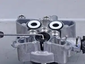
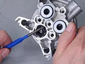
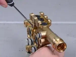
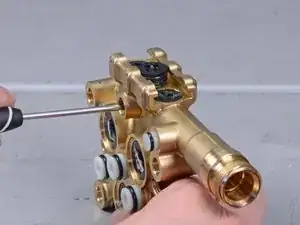
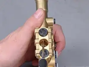
    • Insert an L-shaped pick tool into the connecting channel on each side of the center cylinder.

    • Press upwards to loosen the drain plug.

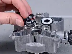
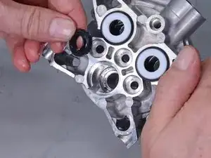
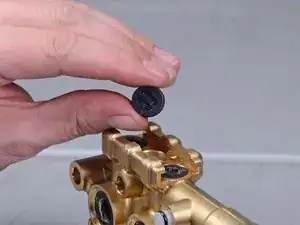
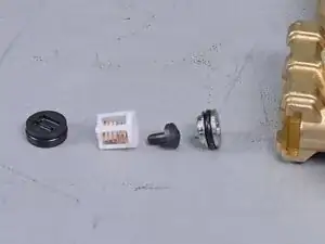
    • Remove the black drain plug and the plastic valve underneath it.

    • Repeat the process for the remaining drain plug and valve.

  53. sbpBAluEsAfDknYx
    sbpBAluEsAfDknYx
    iYZiXmiWEvZVgFK3
    lVBJWkFa3RNGsNeI
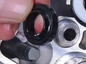
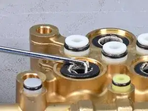
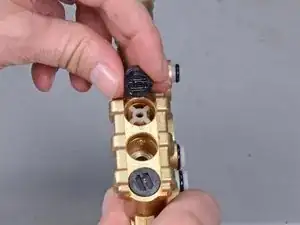
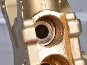
    • It is likely that the metal valve washers did not come out with the plastic valves. Follow this step to remove the metal valve washers from the cylinder head.

    • Use needle-nose pliers to grasp the lip on the metal valve washers.

    • Pull the metal valve washers straight out of the cylinder head.

  54. 2pgDrITRxWaALHUo
    • This photo shows how the pieces stack within the cylinder head.

    • Replace the drain plugs and valves with new ones from the rebuild kit.

    • Drop the valve back into the cylinder head.

    • Press the drain plug back onto the cylinder head.

  55. CWCWDVC5oQWPPhu1
    • Replace the joining piece with a new one from the rebuild kit.

    • At this point, you should have replaced all the parts that came with your rebuild kit. Click here to jump back to step 38, and follow the instructions in reverse order to reassemble the device.

Conclusion

At this point, you should have replaced all the parts that came with your rebuild kit. Click here to jump back to step 38, and follow the instructions in reverse order to reassemble the device.

Arthur Shi

Member since: 03/01/18

248651 Reputation

6 comments

where do I get the part numbers for a pump rebuild kit/ as opposed to ordering the individual items??

DONALD -

what is the part # for the pump rebuild kit.

PIERRE -

2.883-037.0 pump rebuild kit.

BRIAN -

Don’t waste your time. Toss this thing in the trash.

PAUL -

cant seam to be able to order the pump can someone clue me in

LOUIS -

list it as ber.

JEFFREY -