Introduction

Late 2008 MacBook Pros 15 inch models suffer from delamination of the top case which may occur on some models, as the unibody design of the screen isn't really unibody on these early models, but a glued two part item. Heat from computer that is blown onto the hinge slowly softens this glue and it can eventually cause it to separate. Apple had an out-of-warranty case that permitted free replacements of 15-inch Late 2008 MacBook Pro displays, but this case was valid until about 2013-2014.

Upon inspection of several these MacBook Pros 15-inch Late 2008 laptops, I discovered that some of them had very stiff hinges and display opened with too much force. Some of these already had some delamination of the display assembly. As the hinges get stiff, more force is applied on the display which over time causes the already weak glue that holds the outer display housing to break and separate from the back case.

To delay or even prevent the separation, the solution is to lubricate these hinges which is best done with the display removed, also recommended is to remove clutch cover. Only warning is, that sometimes then the hinges can become too soft and may not hold the display at the desired angle.

This guide is also valid for an A1278 Late 2008 MacBook Aluminium 13-inch model, but delamination and stiff hinges are very uncommon on these models (but it does still happen).

  1. SMIreA3NDYKVR4U1
    SMIreA3NDYKVR4U1
    Fn5atRvTUMN1CWVi
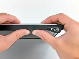
    • With the case closed, place the Unibody top-side down on a flat surface.

    • Depress the grooved side of the access door release latch enough to grab the free end. Lift the release latch until it is vertical.

    The A1286 has no Access Door.!!

    I actually can see no sign of the battery!...

    aguib -

    Quote from aguib:

    The A1286 has no Access Door.!!

    I actually can see no sign of the battery!...

    I assume you have the newer model, with the built-in battery. It's still removable with tools, but these are the wrong instructions for that model.

    lgc90 -

    when will there be a guide for the other unibody macbook pro. that does not have an access door?

    irishking -

    Is there a manual to show, how disasembly the display, i mean, after step 5, to check the display between lcd and aluminiun back case?

    Max

    Max -

    On other guides you state the height of the HD that can be supported, e.g. MacBook Pro 15" Core 2 Duo Model A1211 Hard Drive Replacement , I have read ( but have not confirmed ) that the uni-body MacBook Pro can be fitted with the 750GB and 1TB 12mm drive from Western Digital.

    Can you confirm this?

    Many thanks in advance.

    ahothabeth -

    Quote from SHerwood Ball:

    My display and aluminum casing has separated.

    I don't know if it just snaps back together or does it need to be glued.

    I dropped mine on the carpeted stairs and the display still works.

    I'm hoping I can just snap it back together and that no plastic pieces or teeth of the snapping

    portion have been broken........

    SHerwood Ball -

    When you say "left fan" is this "left when looking at the logic board after turning the computer over and looking it up opening it up" or "left when sitting at the computer keyboard and typing on it"?

    thvv -

    We always use left and right in reference to the computer when you're using it.

    Andrew Optimus Goldheart -

    Directions were great and the worn dc in board was replaced. The hardest part of the procedure is disconnecting the data display cable. A better description of step 21 is to slide the connector parallel to the circuit board towards the outside corner. Reconnecting correctly took several tries.

    I used the tip of the spudger to nudge the corners a little at a time to seat the connector.

    The ribbon connector for the keyboard has to be inserted all the way before seating the retaining cap. It took me three tries . First try power button did not work second try numbers keys did not work.

    Thanks for the directions ...could not have done it with out them!!!

    landryd -

    Hola. Poseo un MacBook Pro Late 2008 y debo cambiarle las cornetas. Me sirve unas cornetas de un MBP Late 2011?

    jegonzalez80 -

    Please read the instructions about removing the bluetooth cable - you CAN work around it, and NOT take off the plug.

    kenneth krabat -

  2. MdrOJSrWnILuwgku
    • The access door should now be raised enough to lift it up and out of the Unibody.

  3. TCsqVADkseQPKnOH
    • Be sure the access door release latch is vertical before proceeding.

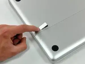
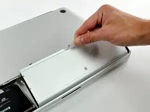
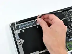
    • Grab the translucent plastic tab and pull the battery up and out of the Unibody.

    • If the latch is depressed it will lock the battery in place.

    Do I need to wait for the battery to charge completely before using the computer (while plugged in)?

    Kaila Potts -

    No. You do not need to charge it completely before removing it.

    Titus (#1579) -

  4. Uk6JATrByBcMWnbH
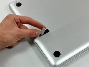
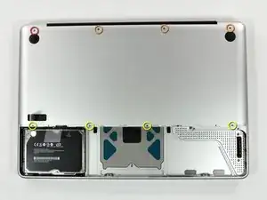
    • Remove the following eight screws securing the lower case to the chassis:

    • One 5.4 mm Phillips screw.

    • Three 14 mm Phillips screws.

    • Four 3.5 mm Phillips screws.

    Hi, My name is Jess I need help asap I accidentally dropped my macbook Pro and i cant find the silver screw for the top left back side, Does any one know if I can replace it with an eye glass screw?? If you can help at all Please e-mail me at Chambliss_jess@yahoo.com thx please help me my bf is going off... ;(

    Jess -

    The fixit PH00 is the wrong screw driver for this entire job. It did not fit in the screws, it was too pointy and caused screws to be rounded off.

    mattrittgers -

  5. JXkONAXLQs5HE3sQ
    • Using both hands, lift and remove the lower case off the upper case.

    About midway along each edge is a snap. To release each snap, gently slide the flat edge of a Spudger under the lower case, then lift the lower case away.

    jonathansturges -

  6. HVZasX6deANqWGgf
    HVZasX6deANqWGgf
    1NVwCkIti1GeHQX2
    • If necessary, peel the EMI gasket off the camera cable connector.

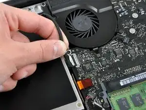
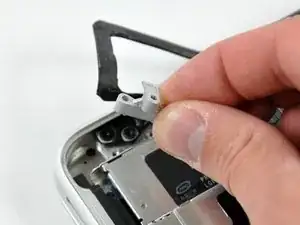
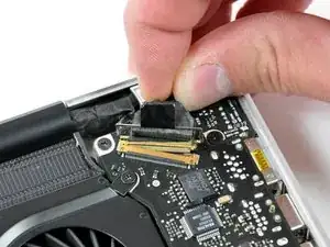
    • Disconnect the camera cable by pulling the male end straight away from its socket toward the optical drive opening.

    • Do not try to lift this connector straight up off the board. Pull the connector parallel to the face of the logic board.

    • Deroute the camera data cable from the channel in the optical drive.

    I have a problem with previous made unprofessional teardown of this mac, and the port that the camera cable is connected to, on the m-board, is cracked, because somebody pulled it straight up .. can someone please, share an idea about the way of fixing it, or maybe a name of the part i need ?

    sanchoser -

  7. dSEtWgrfGVMlpWag
    dSEtWgrfGVMlpWag
    RXOERgWKVIqJucAU
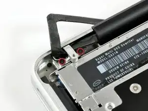
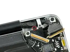
    • Remove the two Phillips screws securing the camera cable bracket to the upper case.

    • The leftmost screw may remain captive in the camera cable.

    • Seperate the camera cable bracket from the camera cable and remove it from the computer.

    For reassembly, it would improve the instructions to note the exact orientation of the camera cable, as well as the LVDS cable, in these steps (7-10). This avoids confusion as to where those cables go when the display is reattached (working steps 11-13 in reverse).

    As viewed from the orientation of the laptop at this point (looking into the motherboard from the underside), these cables are routed ABOVE the mounting plates for the hinges.

    Viewed from the front of the machine (as it would be sitting on the desk in front of you during normal use), they are routed BELOW those plates.

    Haitham -

    On the 13” there’s an additional screw securing the camera cable bracket to the speaker chamber thing. You have to then gently lift up on the speaker chamber corner.

    dgdeckert -

  8. P6TwjLNseoVA3nar
    P6TwjLNseoVA3nar
    D3MMQfb6G3HMrtNk
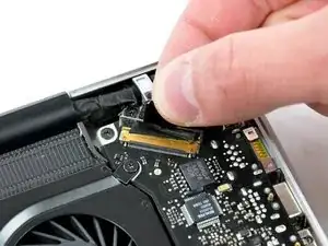
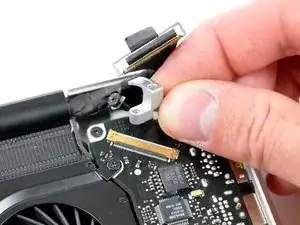
    • Grab the plastic pull tab secured to the LVDS cable lock and rotate it toward the DC-in side of the computer.

    • Pull the LVDS connector straight away from its socket.

    • When disconnecting the LVDS cable, do not pull on the black tab secured to the LVDS cable lock. We recommend wiggling the cable while applying tension to slowly "walk" the connector out of its socket.

  9. uwtcfCdfddrOomvK
    uwtcfCdfddrOomvK
    2JgTDeJoXOKhOwbu
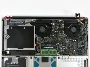
    • Remove the 7 mm Phillips screw from the LVDS cable bracket.

    • This screw may remain captive in the LVDS cable.

    • Lift the LVDS cable bracket out of the upper case.

    On the 13” there are TWO screws securing the LVDS cable bracket, of different lengths.

    dgdeckert -

  10. sBA5JYLAduUuolFr
    • Remove the two outer 6 mm Torx screws securing each side of the display to the upper case (four screws total).

    Ccouldn't make it past step 10 as the two T6 screws on the right stripped. I was using the correct tool, correctly seated, but the screws were simply unwilling to turn and the screw head gave out before they turned at all. The ones on the left came out alright, but there seems to be some type of thread glue on them. Recommendations on how to break that seal without stripping the screw heads might be a good idea. Otherwise - be forewarned.

    Jonathan Field -

    I have the same problem with step 10. Can't remove the screw on the left, it is all damaged.

    Benny Chew -

  11. BmLswTB4RdO2gHyT
    • Open your MacBook Pro so the display is perpendicular to the upper case.

    • Place your opened MacBook Pro on a table as pictured.

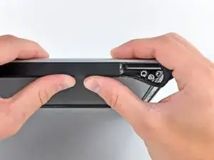
    • While holding the display and upper case together with your other hand, remove the 6 mm Torx screw from the lower display bracket.

    Unlock without removing them , the two remaining center 6mm Torx screws securing the display to the upper case.

    thierry28722 -

  12. AdqCwBUUtefganVr
    • Be sure to hold the display and upper case together with your other hand. Failure to do so may cause the freed display/upper case to fall, potentially damaging each component.

    • Remove the last remaining 6 mm Torx screw securing the display to the upper case.

    One of the Torx screws holding the Display in place failed to come out. I tried too hard and it shredded the head of the screw so there was no physical leverage to the screw driver, so I left it to avoid any further damage.

    So instead I removed ‘not’the torx screw on the computer but the one on the display itself. There are three on the inner part of the screen, two facing the display and the third on the other side. It sled out easily.

    It only added a couple of minutes to my time removing it.

    But a word of caution, you must remove the long plastic housing that holds the cables for the iSight and display, just be gentle and slide it off trying not to snag the cables, it should come off easy.

    cngdoon -

  13. 1hKECZjFToiAQZSF
    1hKECZjFToiAQZSF
    j1EJdXZFIuFoca1y
    6UvZRXDHSPX2qnO5
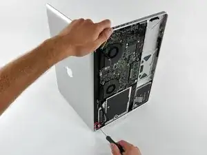
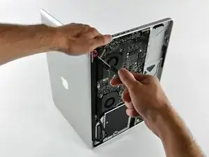
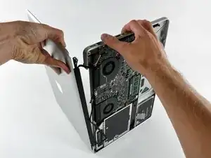
    • Grab the upper case with your right hand and rotate it slightly toward the top of the display so the upper display bracket clears the edge of the upper case.

    • Rotate the display slightly away from the upper case.

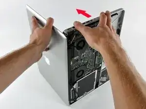
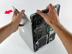
    • Lift the display away from the upper case, minding any brackets or cables that may get caught.

    If I purchase a MBP 15' for parts that has a good top case, LCD and Glass, could I stop at Step 14, replace the entire top case and reverse from Step 13 to put it back together? Or do I need to proceed with steps 14 to 21, loosening the glue, lifting the glass, replacing the LCD?

    jbarrick1 -

    I think you should be good up to just Step 14 if that's the case.

    craig -

    On the 13” just slightly open the display/lid a little more and it’ll fall away without needing to do any of the push forward/away stuff as depicted on the 15” here.

    dgdeckert -

  14. yJgvofMmCSRwPSSA
    yJgvofMmCSRwPSSA
    kVhGXBPJ1FBfIqdt
    • Slide the clutch cover toward the right edge of the display.

    • The clutch cover will move approximately .25" and stop. Do not force it too far to the right.

    • When reinstalling the clutch cover, be sure to slip it over the components protruding from the lower edge of the display about .25" to the right of its final installed position on the display.

  15. 5kiIpVMrrWcdMWl5
    5kiIpVMrrWcdMWl5
    jcXXLW6IWYwkHbKQ
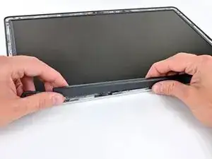
    • Starting at its far left end, rock the clutch cover along its long axis while pulling it away from the clutch hinge.

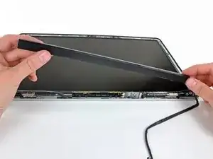
    • Working from right to left, carefully continue to release and lift the clutch along the lower edge of the display assembly.

    • Lift the clutch cover up off the front bezel and set it aside.

    • When reinstalling the clutch cover, be sure to widen the opening when slipping it over the small black plastic cosmetic cover that fills the open end of the clutch cover when it is in place. The cosmetic cover has very thin and delicate plastic arms that hold it to the right clutch hinge.

    • Use a cloth or paper towel to cover the LCD and surroundings as you do not want to get any silicone lubricant there.

    • Spray small amount of silicone lubricant onto the display hinges, where the silver part is.

    • While you are there, check the three screws that hold the hinges for any play and re-tighten them if necessary.

    • These screws sometimes come loose after years of everyday use, so it is a good idea to check the tightness anyway

    • Don't spray too much of lubricant onto the hinges, as it might puddle up and get trapped underneath the LCD!

    • Reassemble the laptop, starting with clutch cover.

    • Open and close the display a few times while checking if the display closes and opens more smoothly.

    • If you feel that lubrication did not help much, you can try to lubricate it again. But don't overdo it.

Conclusion

To reassemble your device, follow these instructions in reverse order.

oldnwstf

Member since: 06/10/13

441 Reputation

0 comments