Introduction

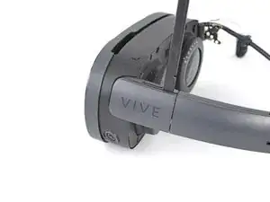
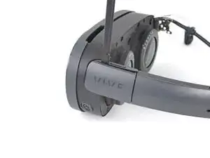
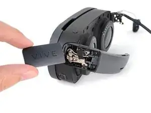
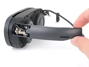
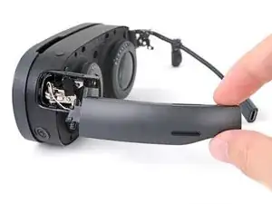
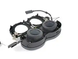
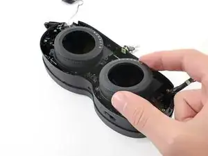
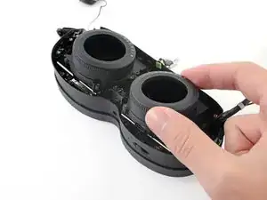
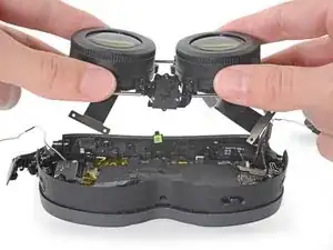
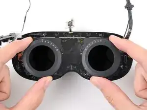
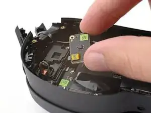
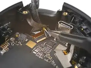
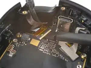
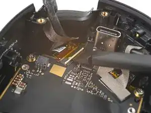
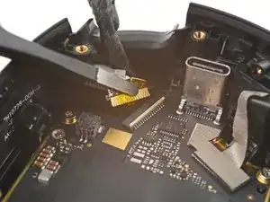
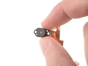
Use this guide to replace the depth sensor in your HTC Vive XR Elite.

  1. hnuvnhyLbDuUMlEV
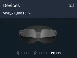
    • Before starting this repair, discharge the batteries in your headset below 25%. A charged battery may leak dangerous chemicals or catch fire if damaged.

    • Playing Half Life: Alyx will do the trick!

    • The Vive XR Elite has a proximity sensor that puts the headset in standby mode to save battery when it isn't in use. To drain the battery faster you'll need to use the headset.

  2. bjdKIqZEAJNajlep
    bjdKIqZEAJNajlep
    3VjJPLXEBPp4fbyY
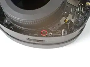
    • Disconnect the USB-C power cable.

  3. djQJRxo1UMDJPChO
    djQJRxo1UMDJPChO
    KnkAiqJqPWDQIDkm
    nbcyDDyYAo5yjbfW
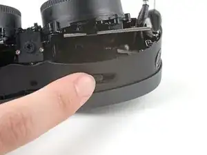
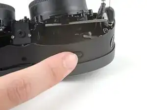
    • Press the release button on the right battery cradle temple slot.

    • Pull the battery cradle away from the right temple slot to disconnect it.

  4. bIiBBtIfTRCUuMrA
    bIiBBtIfTRCUuMrA
    QxUyfeDH6mhxPkIj
    6Q3eGtEXZUOciDtU
    • Repeat the previous step for the left temple slot.

  5. VUFb3hOjRuSUD3ZX
    • Separate the headset and battery cradle.

  6. pSTPNKEBlSi21oNY
    pSTPNKEBlSi21oNY
    UxPQGecZf5uMexVE
    jwj1Uv1MiFemERPO
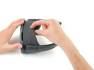
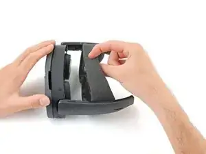
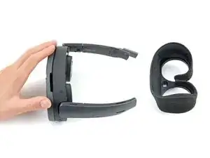
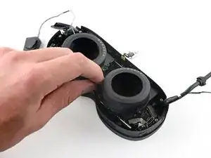
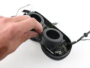
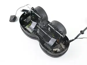
    • The face cushion is attached to the headset with two magnets. You'll feel the pull of the magnets as you remove it.

    • Grip the middle of the face cushion with your fingers and pull back to remove it.

  7. XaIvStoZ6iTiIZYn
    XaIvStoZ6iTiIZYn
    IGqKRXwDolpVo1Wy
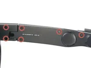
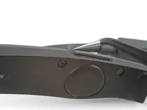
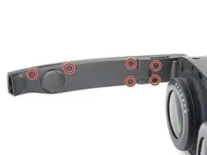
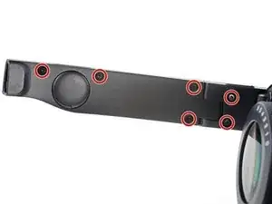
    • Use tweezers to remove the six screw covers from the right temple.

  8. WQonU2SLP4DgyUCP
    WQonU2SLP4DgyUCP
    qnUUxjjJ2oa3GGEb
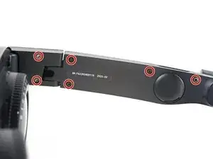
    • Use a T5 Torx screwdriver to remove the six 4.9 mm‑long screws securing the two right temple halves.

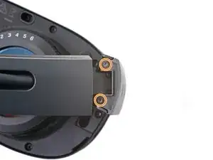
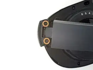
    • Use a T5 Torx screwdriver to remove the two 3.5 mm‑long screws securing the right hinge cover.

  9. thQGsLqVDCK12RtP
    thQGsLqVDCK12RtP
    iWxhQpskxFDRJrYB
    gjoZMZeZ1SDVOKvH
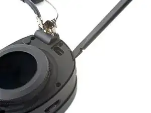
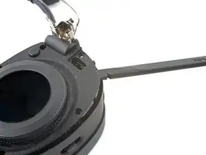
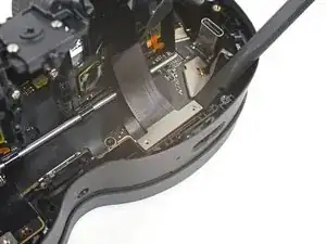
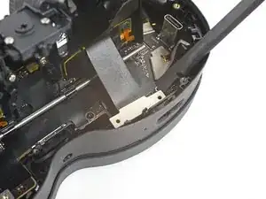
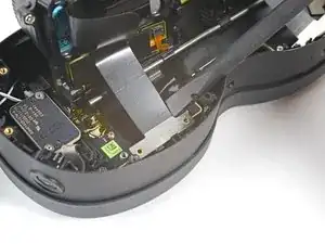
    • Insert the flat end of a spudger in the gap between the right outer and inner hinge covers.

    • Slide the spudger along the gap to separate the clips securing the outer hinge cover.

    • Remove the outer hinge cover.

  10. YcAIPhneuy6pVN5F
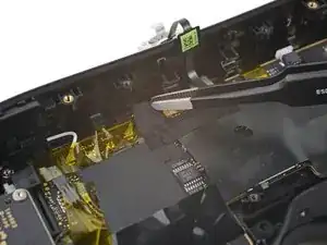
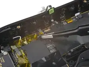
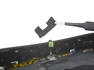
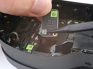
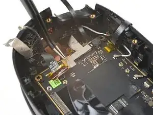
    YcAIPhneuy6pVN5F
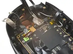
    SrMMgGWUHEPWDhZB
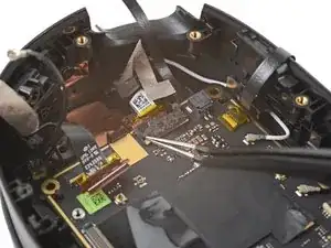
    liEeWFnVPOySItt1
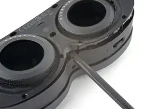
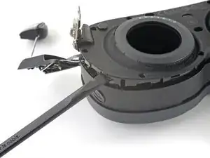
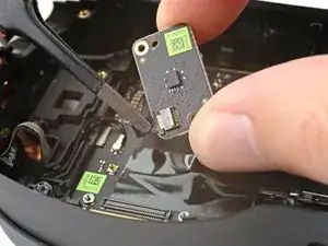
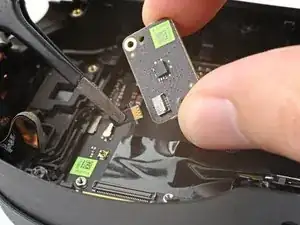
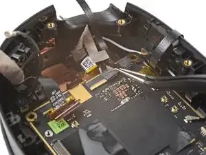
    • Insert the flat end of a spudger in the gap between the outer and inner temple.

    • Slide the spudger along the gap to separate the clips securing the outer temple.

  11. R4ZN35Z3AvkPFyWB
    R4ZN35Z3AvkPFyWB
    pQPILeKl2RE5bfpr
    cKkeTUals2qO3kS3
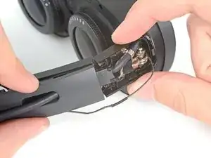
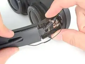
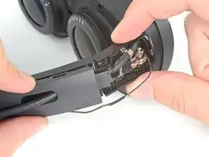
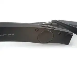
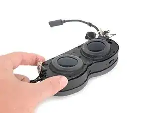
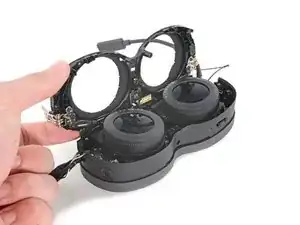
    • Slide the top of the outer temple out of its slot in the hinge.

  12. XqUjJg1wis2RKipy
    XqUjJg1wis2RKipy
    It1BdRsNOBPFnDQd
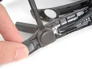
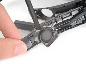
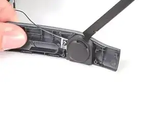
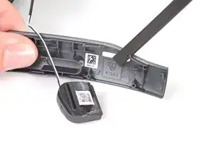
    • The speaker is lightly adhered to the outer temple.

    • Rotate the outer temple towards you to access the speaker.

    • Slide the flat end of a spudger under the speaker to separate its adhesive.

    • During reassembly, if your speaker adhesive isn't sticky, use double-sided tape to re-adhere the speaker to the outer temple.

  13. FSLxGOCRPvwHyADk
    FSLxGOCRPvwHyADk
    bj5OhNOiUgWyB5dL
    A54TE4a2pRbv4DTY
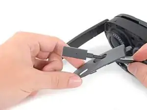
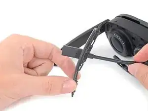
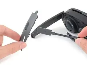
    • Thread the outer temple off of the USB‑C cable and remove it.

  14. RmDxLoG2QJDoQVYJ
    RmDxLoG2QJDoQVYJ
    NdecrhcjhrtJTLrp
    • Pull the inner temple out of its slot in the hinge and remove it.

  15. nGuDCfVY3oQeXVmP
    nGuDCfVY3oQeXVmP
    xFTX3pPYn4tqFWrq
    • Use tweezers to peel back the black tape covering one of the inner hinge cover screws.

  16. nDpdvJM5ykwXgCkd
    • Use a T5 Torx screwdriver to remove the two screws securing the inner hinge cover:

    • One 3.1 mm‑long screw

    • One 4.9 mm‑long screw

  17. jJRbau1wCBxo4WkE
    jJRbau1wCBxo4WkE
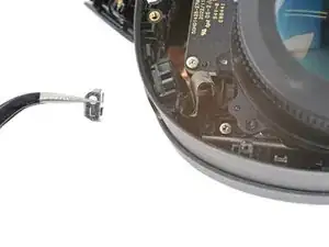
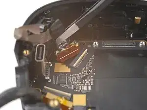
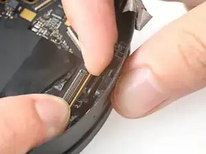
    GBUj2UOeuLoj6Jox
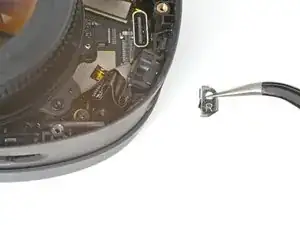
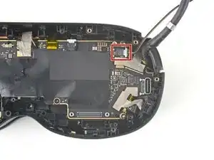
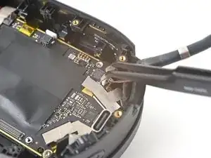
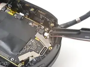
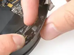
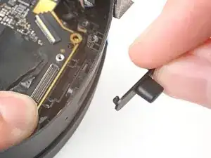
    d1KnxWG6GRCESKUq
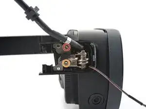
    • Rotate the inner hinge cover off its groove in the frame.

    • Thread the inner hinge cover off of the USB-C and speaker cables and remove it.

  18. RGyK43ATZeXochK3
    RGyK43ATZeXochK3
    ZIXIys4ohMnuvQJs
    • Use tweezers to remove the six screw covers from the left temple.

  19. hfDkILsJ2NpLbFtf
    hfDkILsJ2NpLbFtf
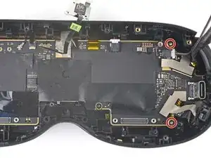
    5HvRELCVEFX1JGje
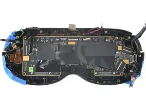
    • Use a T5 Torx screwdriver to remove the six 4.9 mm‑long screws securing the two left temple halves.

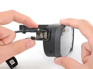
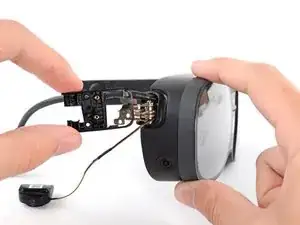
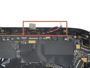
    • Use a T5 Torx screwdriver to remove the two 3.5 mm‑long screws securing the left hinge cover.

  20. SEnSBqM4p4alrC3o
    SEnSBqM4p4alrC3o
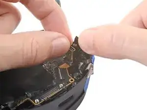
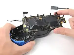
    lMERK5H3WAxoxpby
    oG2cYdUhbbGavKNL
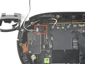
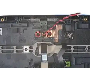
    • Insert the flat end of a spudger in the gap between the left outer and inner hinge covers.

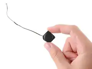
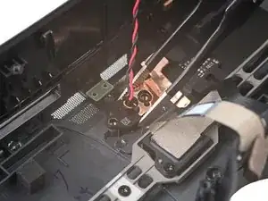
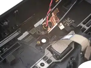
    • Slide the spudger along the gap to separate the clips securing the outer hinge cover.

    • Remove the outer hinge cover.

  21. yn44LGpZrHFFNqZM
    yn44LGpZrHFFNqZM
    YDWOjcCvyoj63MPE
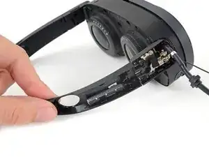
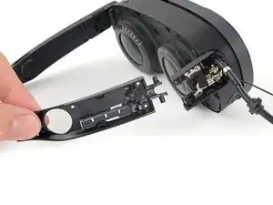
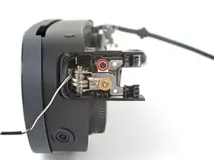
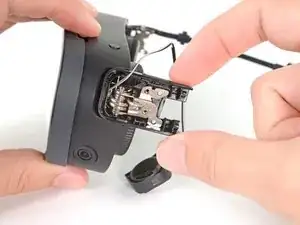
    • Pull the left temple out of its slot in the hinge.

    • Don't try to fully remove it yet, as it's still connected by a cable.

  22. MANC1WLyxK4Dp4Gs
    MANC1WLyxK4Dp4Gs
    1YickegjUShM2i5X
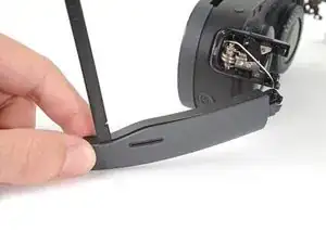
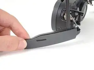
    • Insert the flat end of a spudger in the gap between the outer and inner temple.

    • Slide the spudger along the gap to separate the plastic clips securing the outer temple.

  23. rkfXbOSSnCwkfp3c
    rkfXbOSSnCwkfp3c
    2bfLc5yIFUDXoxYY
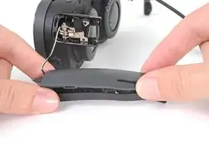
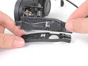
    • Pull the outer temple off of its inner half to completely release its plastic clips.

  24. MGoNTGqW2cDZVpmT
    MGoNTGqW2cDZVpmT
    lHPH1AEbY6IWY5VF
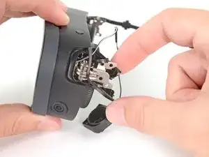
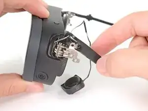
    • The speaker is lightly adhered to the outer temple.

    • Slide the flat end of a spudger under the speaker to separate its adhesive.

    • Let the speaker rest next to the headset before continuing.

    • During reassembly, if your speaker adhesive isn't sticky, use Tesa 61395 Tape to re-adhere the speaker to the outer temple.

  25. sD4nwNEfUOnyy4t4
    sD4nwNEfUOnyy4t4
    H61puTtk2Z14OxNV
    • Use tweezers to peel back the black tape covering one of the inner hinge cover screws.

  26. x4UZQhEZOCKh3XVQ
    • Use a T5 Torx screwdriver to remove the two screws securing the inner hinge cover:

    • One 3.5 mm‑long screw

    • One 4.9 mm‑long screw

  27. ZL6O62smkwUfWnMF
    ZL6O62smkwUfWnMF
    2YTQ55qsUGUnBoM3
    ADNMq14ACsxHXXZT
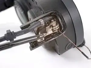
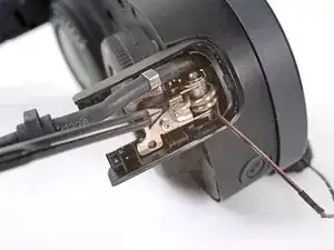
    • Don't fully remove the inner hinge cover, as it's connected by the volume button cable.

    • Rotate the inner hinge cover off its groove in the frame.

    • Let the cover hang off its volume button cable for now.

  28. lh5AvyXjKSmMDZhO
    lh5AvyXjKSmMDZhO
    EyXQiq1hRG3UkI6T
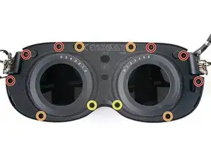
    • Use a T5 Torx screwdriver to remove the 12 screws securing the face plate:

    • Six 3.5 mm‑long screws

    • Four 4.9 mm‑long screws

    • Two 6.5 mm‑long screws

    • There are two magnets at the top corners of the face plate. As you remove nearby screws, they might stick to them.

  29. bBpb1RbWOlk3kUbo
    bBpb1RbWOlk3kUbo
    FJPcd5qs5XALi3ZJ
    • Insert the flat end of the spudger in the gap between the frame and the bottom right corner of the face cover.

    • Pry up with the spudger to release the clips securing the face cover.

  30. YgtYhMRgqIO1Y6R1
    YgtYhMRgqIO1Y6R1
    1ST3iHi2xjXMxvPH
    • Repeat the prying process for the middle and bottom left portions of the face cover.

  31. AP1bLUNyxnHpyfkI
    AP1bLUNyxnHpyfkI
    hMRJaFlwmF4PBjUJ
    ZwsRGgGTwDcosI2N
    • Don't fully remove the face cover completely, as it's connected by the proximity sensor cable.

    • Lift the face cover and rotate it over the top of the frame.

    • Lay the face cover face up before continuing.

  32. AgInJiRDj1PJGFNp
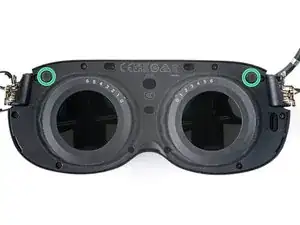
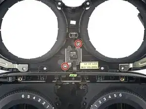
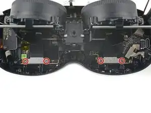
    • Use a T5 Torx screwdriver to remove the two 3.3 mm‑long screws securing the proximity sensor cable.

  33. BTWQTX3NXPhZjFs2
    BTWQTX3NXPhZjFs2
    xnApYyuiHuBciGHY
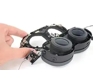
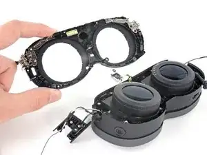
    • Remove the face cover.

  34. RJ41EEQcExSEijFY
    RJ41EEQcExSEijFY
    Hd3XPRYokLupK4cv
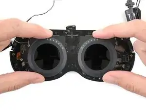
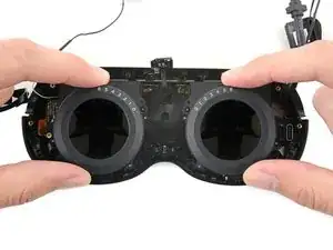
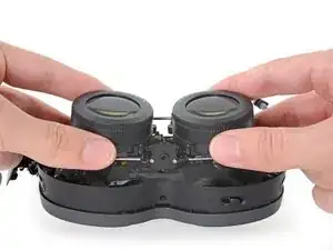
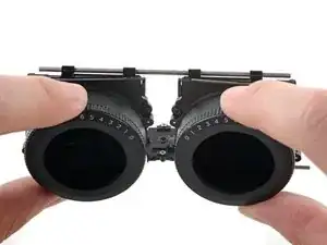
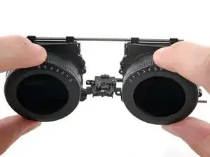
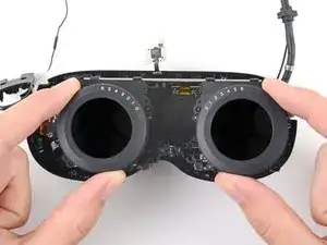
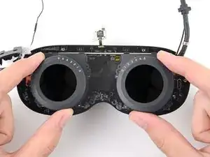
    • Pull the two lenses outward so they're as far apart as possible.

  35. HOvj4ql1hw3U4X2w
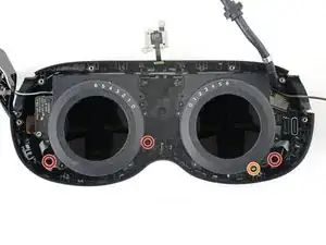
    • Use a T5 Torx screwdriver to remove the four screws securing the lens assembly:

    • Three 4.9 mm‑long screws

    • One 3.3 mm‑long screw

  36. GskDf54K3pOrn2wO
    GskDf54K3pOrn2wO
    2rZmqDLkPDHFyi1G
    BdsNUyv1R1MbrxkO
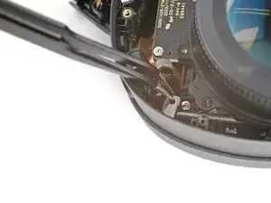
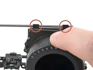
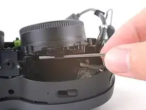
    • The screw brackets are secured with clips and adhesive.

    • Use tweezers to pull the left screw bracket of its post in the frame.

    • This may require some force. Be careful not to scratch any surrounding components.

    • Repeat this process for the right bracket.

    • During reassembly, use tweezers to align the brackets on their posts. Press down with the flat end of a spudger to engage and re-adhere the clips.

  37. uHdmSAMhIYh2bBuW
    uHdmSAMhIYh2bBuW
    pwUwoDv5kKfrDqch
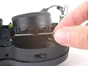
    • Lift the bottom of the lens assembly up to separate the bottom rails from their slots in the frame.

  38. KJ2eYM6HrIYY5ePt
    KJ2eYM6HrIYY5ePt
    QPsW1sGZPeGWpsmv
    mAcqYHPdcNyOADgj
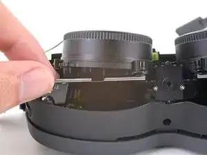
    • Pull the lens assembly upwards to separate the top rails from their slots in the frame.

    • Rotate the lens assembly towards the top of the frame so it sits upright with its cable connectors exposed.

  39. GtTL2jHFjFGb4ZSv
    • Use a T5 Torx screwdriver to remove the four 3.4 mm‑long screws securing the lens assembly cables.

  40. sPUtbuGYqSoSPMYe
    sPUtbuGYqSoSPMYe
    K4TZHVikb13B1PPL
    oODTbBwY4ERRqUGo
    • Use the flat end of a spudger to pry up and disconnect the lens assembly cable connector.

    • Repeat this procedure for the other connector.

    • To re-attach press connectors like this one, carefully align and press down on one side until it clicks into place, then repeat on the other side. Don't press down on the middle. If the connector is misaligned, the pins can bend, causing permanent damage.

  41. DEKmcKdxEHLT4MoH
    DEKmcKdxEHLT4MoH
    dEF4eZEgG3xSAhnW
    • Lift up and remove the lens assembly.

  42. CJfrx6rkUDXOVrub
    CJfrx6rkUDXOVrub
    SuGXQRcQWCLDmXIw
    FpqBxdTQfPAJsMq5
    • The next four steps demonstrate how to secure the lens assembly to the frame during reassembly.

    • In order for the lens assembly to rest in the frame properly, it needs to align with a peg in the IPD (interpupillary distance) slider.

    • Before reinstalling the lens assembly, push the IPD slider to its right-most position.

  43. xvZGXKgmSFlPvZew
    xvZGXKgmSFlPvZew
    ALIZeoAGeHEdSIgI
    X4Pf3g2lUqC5CiKp
    • Pull the lens assembly outward until its plastic clips sit close to the end of the top rails.

    • You may need to push and pull the top rail so it sits evenly across the plastic clips.

  44. TdRNCIXyLDDkoMjy
    TdRNCIXyLDDkoMjy
    ItN5VTKtpNLNT363
    hoSrNMZAThJpbMwa
    • Push the bottom rails inwards as far as they will go.

  45. 5YPf421IvZ4y4yJt
    5YPf421IvZ4y4yJt
    beTipaWTxHQ1i3qX
    xYDGM4OILsYv5NsS
    • To secure the lens assembly into the frame:

    • Slide the top left rail into its slot.

    • Align the other rails.

    • Press the lens assembly into place, making sure to realign the center peg.

  46. aePqPyeCmjt5ilos
    aePqPyeCmjt5ilos
    MGEIk1IDEDxrI4JV
    acoGDKPEVXAHUeCE
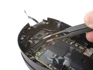
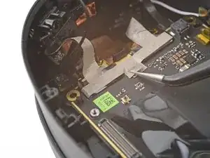
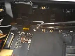
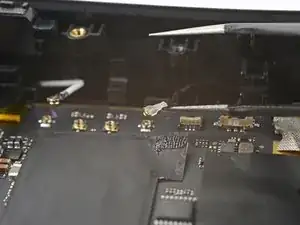
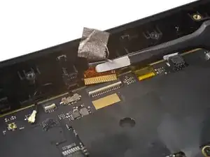
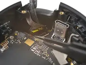
    • Use tweezers to peel off the black tape covering the proximity sensor connector.

  47. ZsMFRAwJUi61X6jG
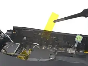
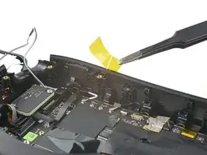
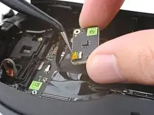
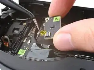
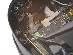
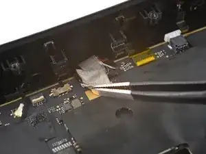
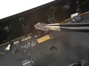
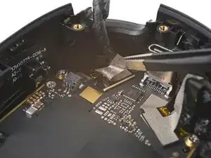
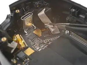
    • Peel off the yellow tape covering the proximity sensor connector.

  48. gDfcyBEImW65iPMB
    gDfcyBEImW65iPMB
    eNs6CeeURjUgcNCC
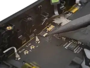
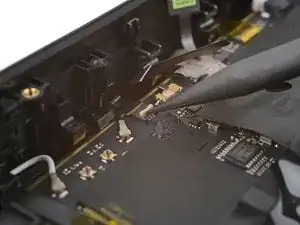
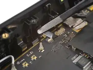
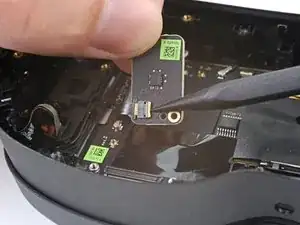
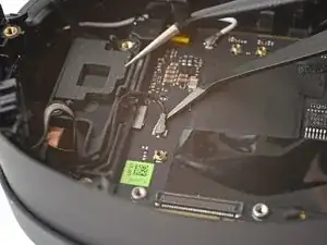
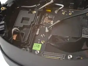
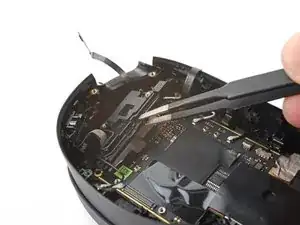
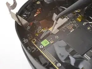
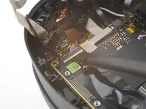
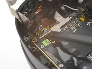
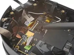
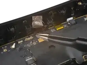
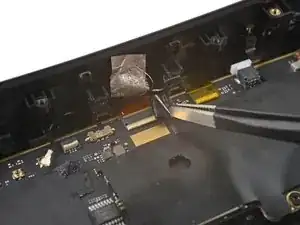
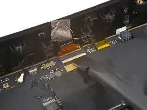
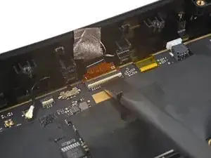
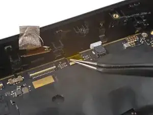
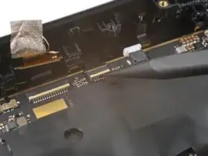
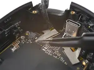
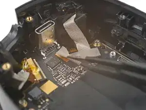
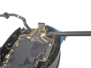
    • Use the point of a spudger to lift up the locking flap on the proximity sensor ZIF connector.

  49. SFVh5yfEydKXL1gJ
    SFVh5yfEydKXL1gJ
    BJQajQnDqXCOZEXj
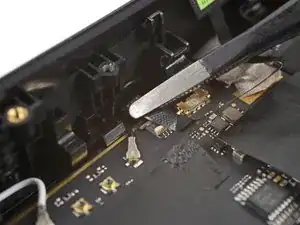
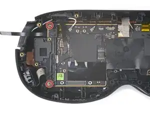
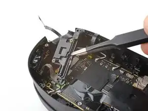
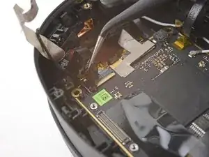
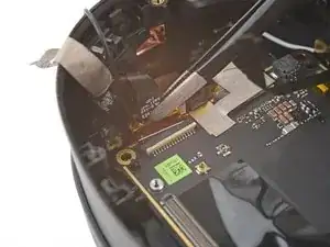
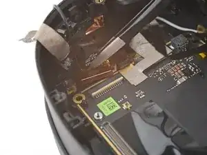
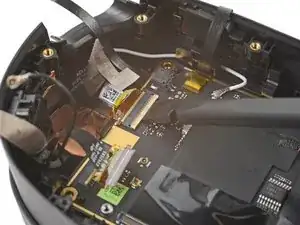
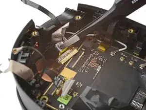
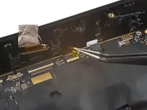
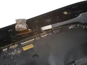
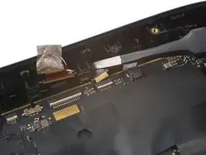
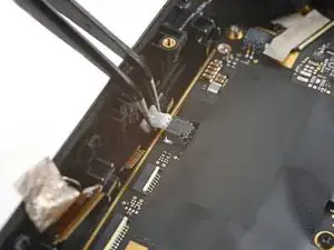
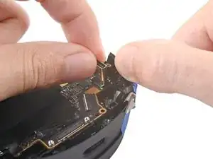
    • Use tweezers to pull the proximity sensor cable out of its slot in the motherboard.

  50. HsT1DPpoMayiSok5
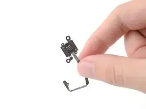
    • Remove the proximity sensor.

  51. EjPPBDbWuIQDuXiy
    EjPPBDbWuIQDuXiy
    I6V2rigdGWS5r2GI
    NUisiOcfLQY2SnYG
    • Peel off the yellow tape covering the motion sensor cable.

  52. nQWoeQFcXSDNGkDZ
    • Use a T5 Torx screwdriver to remove the two 3.4 mm‑long screws securing the motion sensor.

  53. FUInDCCFa1mdZ5GU
    FUInDCCFa1mdZ5GU
    OCYjymDVkiUvM6p6
    YCvpQ5UJSVQRPbCh
    • Don't try to fully remove the motion sensor yet, as it's still connected by a cable.

    • Lift the motion sensor off its pegs in the frame.

    • Flip over the motion sensor and lay it on the frame before continuing.

  54. F1tOpAWyUa6ByhaO
    F1tOpAWyUa6ByhaO
    yklulbpKgJlUj3RB
    • Peel off the yellow tape covering the motion sensor cable connector.

  55. MTSApl12TYEdpE6E
    MTSApl12TYEdpE6E
    NdJ1pfYq2b1fC5UE
    • Use the point of a spudger to lift up the locking flap on the motion sensor ZIF connector.

  56. QDlMtOYRLhITrNkS
    QDlMtOYRLhITrNkS
    YyZPMTNmeUbDYZLI
    • Use tweezers to pull the motion sensor cable connector out of its slot.

    • Remove the motion sensor.

  57. Fy1HBc1m4wBT1xMR
    Fy1HBc1m4wBT1xMR
    cRrZgxFWQtIWvNJL
    m4YhYE4KiZGgwvqT
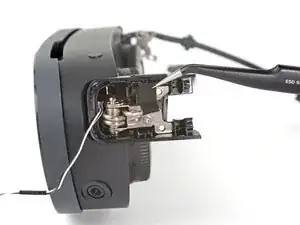
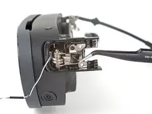
    • Use tweezers to pull the right speaker connector out of its socket.

    • If you're having trouble, try rocking the connector side-to-side to help loosen it.

  58. BUQOBjyP4DCu3lLK
    • Remove the right speaker.

  59. CDrZGiEfiDVakZDN
    CDrZGiEfiDVakZDN
    C3Cf5cJXdIP3E2xf
    SgkK6scY1XSCvDnN
    • Use tweezers to pull the left speaker connector out of its socket.

    • If you're having trouble, try rocking the connector side-to-side to help loosen it.

  60. aeNAhqGIebUWrfDX
    • Remove the left speaker.

  61. qlwkLNDfJSHjtCHP
    qlwkLNDfJSHjtCHP
    jaYQCpey6BFo3Ob2
    • The volume button cable is lightly adhered to the left inner hinge cover.

    • Insert one arm of your tweezers between the volume button cable and the hinge cover.

    • Pry away from the hinge cover to separate the adhesive.

  62. brMKf2SOrdAKtQqI
    brMKf2SOrdAKtQqI
    4lAMALAxRYpLowDw
    HWiyqd5vFvEehBHQ
    • Use your tweezers to pull the volume button cable out of its slot in the hinge cover.

  63. 5tC2GjkCtQwrnvLh
    5tC2GjkCtQwrnvLh
    QIoehJKnH3PgTq6m
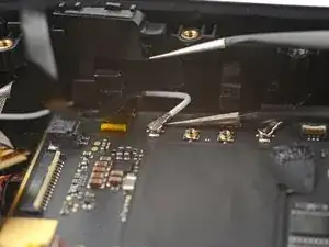
    • Use one arm of your tweezers to pry up and disconnect the bottom left antenna cable.

    • During reassembly, these can be tricky to reconnect. Hold the connector in place over its socket and press down with the flat end of a spudger. The connector should snap into place.

  64. 4Ah4D2KQ1JnBMKN1
    4Ah4D2KQ1JnBMKN1
    1WHkBD3hOQik3DoO
  65. lCiREqRJ2CquN6Kw
    • Use a T5 Torx screwdriver to remove the two 4.9 mm‑long screws securing the motion sensor bracket.

  66. Wmc2bWnHUgsG1VPO
    Wmc2bWnHUgsG1VPO
    hmGxAVaFCgNc5d2u
    PJKGHZTc3AoODZa5
    • Lift the motion sensor off its pegs on the motherboard.

    • Remove the motion sensor bracket.

  67. lSuwd4mA2uUGcli4
    lSuwd4mA2uUGcli4
    xodL25TeSstZlMtD
    • Use tweezers to peel back the gray conductive tape covering the left side‑camera ZIF connector.

  68. gNeDgaYUrDgggESb
    gNeDgaYUrDgggESb
    kKrbGSCeAkffZNZV
    • Use tweezers to peel off the black tape covering the left side‑camera ZIF connector.

  69. WZ4Z1M1itfph2TBU
    WZ4Z1M1itfph2TBU
    PMFRiDf5uOQVdOPC
    • Use flat end of a spudger to lift up the locking flap on the left side‑camera ZIF connector.

  70. HamWb4vXd1nKxIaG
    HamWb4vXd1nKxIaG
    lOagqNDSVQ3PLGxQ
    • Use tweezers to pull the left side‑camera cable connector out of its slot in the motherboard.

  71. DW4BbbVCOVy5K5T1
    DW4BbbVCOVy5K5T1
    3vQoDXKQSknAIZAl
    • Use tweezers to peel back the gray conductive tape covering the left tracking camera ZIF connector.

  72. Ns2WeSTRkFBNLYI4
    Ns2WeSTRkFBNLYI4
    hN25CaYgxJYEI4WV
    • Use tweezers to peel off the black tape covering the left tracking camera ZIF connector.

  73. BXMJr3WyMLKVCwlb
    BXMJr3WyMLKVCwlb
    dNAhtduOAHnnUVMw
    • Use a spudger to lift up the locking flap on the left tracking camera ZIF connector.

  74. hOtVXMMbJucnDZ61
    • Use tweezers to pull the left tracking camera cable connector out of its slot in the motherboard.

  75. WLCnUL1eDLpPGwm4
    WLCnUL1eDLpPGwm4
    b5AXpMG3XKjfMv5P
    6rgra2clhhGIqOTo
  76. K1m2qlPAxDfaKqLN
    K1m2qlPAxDfaKqLN
    QHYxmTEMMq2LUrGV
  77. uBXOqJGtXKOqEQfn
    uBXOqJGtXKOqEQfn
    ADSD4Wgak6AFmM6Q
    • Use tweezers to peel off the black tape covering the pass-through camera ZIF connector.

  78. L4FinegtOW11FTPe
    L4FinegtOW11FTPe
    MxCgYanpC1AbHong
    • Use a spudger to lift up the locking flap on the pass-through camera ZIF connector.

  79. yLInqafnKAAoRfgS
    • Use tweezers to pull the pass-through camera cable connector out of its slot in the motherboard.

  80. DGmsJW6TeqYdVACW
    DGmsJW6TeqYdVACW
    GxFUKNP6PCRICAUN
  81. dXDSplEWskhkwa3h
    dXDSplEWskhkwa3h
    OadQrSFOqVTrLYEF
    • Use the point of a spudger to lift up the locking flap on the microphone ZIF connector.

  82. 1NOmASn5ituQkutB
    1NOmASn5ituQkutB
    NBAMCa2GwiZPwkYl
    • Use tweezers to pull the microphone cable connector out of its slot in the motherboard.

  83. V4JfXPBrH5gmZDqW
    V4JfXPBrH5gmZDqW
    adcKnQgRUlDkdLJj
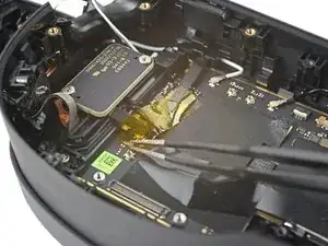
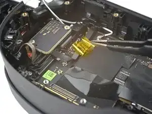
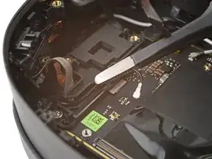
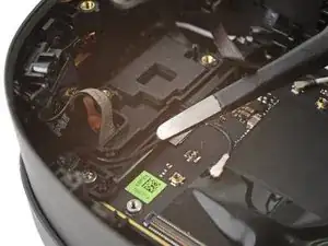
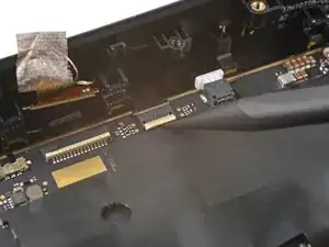
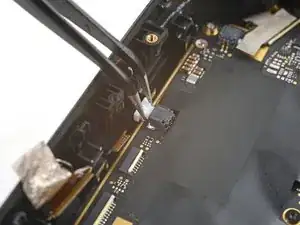
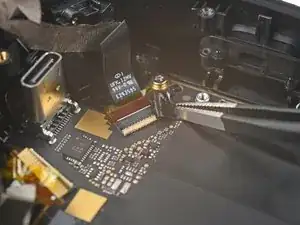
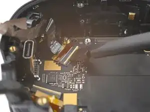
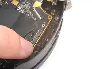
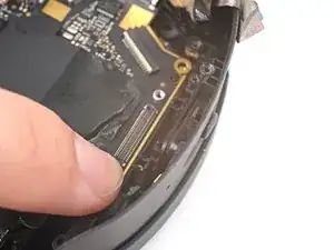
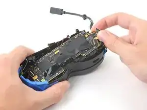
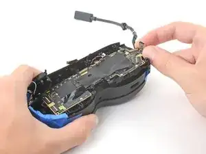
    • Use tweezers to pull the depth sensor cable connector out of its slot in the motherboard.

  84. f3RuZDxeHNv3aaIY
    f3RuZDxeHNv3aaIY
    WfNrG6YP6ntItdIa
    • Use tweezers to peel back the gray conductive tape covering the right tracking camera ZIF connector.

  85. YjSG2fVInYKOjWZE
    YjSG2fVInYKOjWZE
    FUFwraiqdRDNidmH
    • Use tweezers to peel off the black tape covering the right tracking camera ZIF connector.

  86. etcGfttcgYlNSAI1
    etcGfttcgYlNSAI1
    xcN4YiAyk4CDaeiV
    • Use a spudger to lift up the locking flap on the right tracking camera ZIF connector.

  87. oxgrIIaBsbZTlLIG
    • Use tweezers to pull the right tracking camera cable connector out of its slot.

  88. 1Hmh2gJPhq1hpRrN
    1Hmh2gJPhq1hpRrN
    DFeYN3NI6byRAmP5
    • Use tweezers to peel back the gray conductive tape covering the right side‑camera ZIF connector.

  89. mOInvRyGTARrLhix
    mOInvRyGTARrLhix
    iAYTcu4hpKwICht5
    • Use tweezers to peel off the black tape covering the right side‑camera ZIF connector.

  90. LbHnqcBAvawymcX4
    LbHnqcBAvawymcX4
    Avbf3DEMIkiXTKSn
    • Use a spudger to lift up the locking flap on the right side-camera ZIF connector.

  91. or1NkBnbwfRNOOpx
    • Use tweezers to pull the right side‑camera cable connector out of its slot.

  92. RCThYvUJ4flDtj1M
    • Use a T5 Torx screwdriver to remove the two 4.9 mm‑long screws securing the motherboard frame.

  93. LNkhQIpmByVA2I5C
    LNkhQIpmByVA2I5C
    dmYOtZQBWEBvRESB
    • Use tape with light adhesive, such as painter's tape, to keep the left and right side cables away from the motherboard.

    • The cables near the top edge need slack for the motherboard to rest properly in the frame. Avoid taping them tightly—or avoid taping them altogether.

  94. jWOTYTPpxZjAHsbI
    jWOTYTPpxZjAHsbI
    WamWotI4Uh5tNLKG
    • Lift the power button out of its slot in the frame.

    • Don't remove the button completely, as it's still attached by a cable.

  95. 2Bpr4lUGmxvQIw6M
    2Bpr4lUGmxvQIw6M
    k6DW5VBA4QUODTMD
    • Press down the bottom right corner of the motherboard so its edge rests under the IPD slider.

  96. 2KmXoyaJHajlHLWD
    2KmXoyaJHajlHLWD
    2M3SAKpJB4HCD6dH
    2bU4KMKEY4i65hRE
    • While pressing down on the motherboard, push the IPD slider out of its slot in the frame.

    • Remove the IPD slider.

  97. k1pv6GIuVgiUUwSE
    k1pv6GIuVgiUUwSE
    PGvLMCFyKDEvf1sg
    adkmQdTXlTsQERxV
    • Grip the USB-C port with one hand and the right side of the frame with the other.

    • Pull the frame outward while lifting the motherboard assembly until it clears its slot next to the right side‑camera.

    • Use a spudger to pry up the motherboard assembly until its right side completely clears the frame.

  98. pLsHg1JJyBJSuaFk
    pLsHg1JJyBJSuaFk
    Bi2qHhonuEUnFvrA
    XEULKPU3YLGQE6dw
    • Pull the right side of the motherboard assembly toward the bottom edge of the device to separate it from the frame.

    • Remove the motherboard assembly.

    • During reassembly, make sure the cables stay above the motherboard assembly as you reinstall it.

  99. QxQkIPmHqIjWJMWI
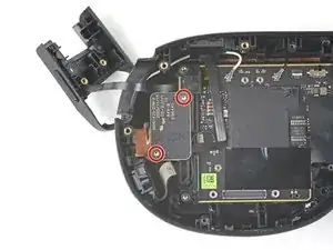
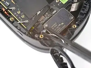
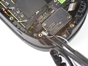
    • Use a T5 Torx screwdriver to remove the two 3.5 mm‑long screws securing the depth sensor.

  100. HqvDqHbknMgjInC2
    HqvDqHbknMgjInC2
    11YtPM23IA1eUiPw
    qxUHQpfDrxlD1TNB
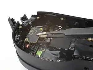
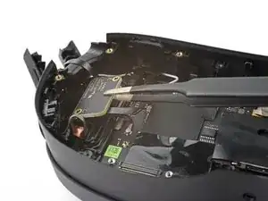
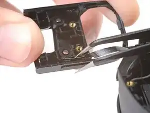
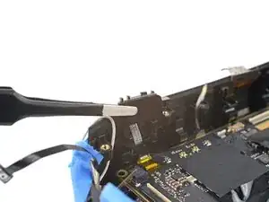
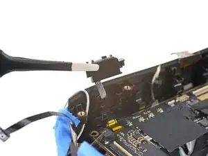
    • Use tweezers to pull the depth sensor off of its two alignment pegs in the frame.

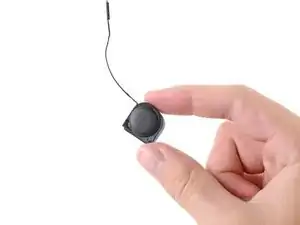
    • Remove the depth sensor.

Conclusion

Compare your new replacement part to the original part—you may need to transfer remaining components or remove adhesive backings from the new part before installing.

To reassemble your device, follow these instructions in reverse order.

Take your e-waste to an R2 or e-Stewards certified recycler.

Repair didn’t go as planned? Try some basic troubleshooting, or ask our Answers Community for help.
Alex Diaz-Kokaisl

Member since: 16/01/22

117875 Reputation

0 comments