Introduction

Replace the camera board in your HP Mini 1000.

  1. NlpLgN4cG3NHRYVi
    NlpLgN4cG3NHRYVi
    MQhnkA31HbymZ4wU
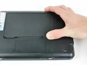
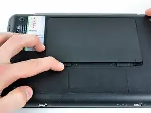
    • With the case closed, place the Mini 1000 top-side down on a flat surface.

    • Push both of the battery release latches toward each other.

  2. NZ5Q6JEwcTdPOkRi
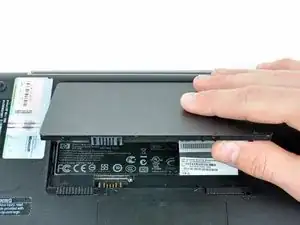
    • Lift the battery out of the Mini 1000 from the edge closest to the release latches.

    Need a battery and a keyboard.

    valfin.teach -

  3. Nt4YqS6mouYOFyiU
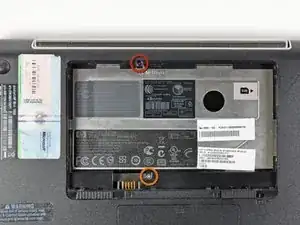
    • Remove the following two screws:

    • One 6 mm Phillips screw

    • One 4 mm Phillips screw

  4. FIsdumu2cDZMnRp3
    FIsdumu2cDZMnRp3
    YFsIfEWJjBrW1eas
    QxjrAtt2lQbxylQI
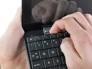
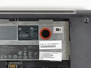
    • To facilitate the removal of the keyboard, it is recommended to push the keyboard outwards with one hand through the opening (highlighted in the third picture) located on the backside of the Mini 1000.

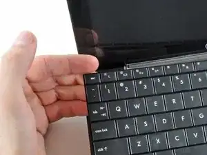
    • While pushing through the opening with one hand, grasp the left upper edge with the other hand and slightly pull the keyboard towards you.

    • Once an opening has been established, grasp the keyboard and slowly lift it upwards along the upper perimeter of the top edge.

  5. fCAQVJJdNAZrHVjH
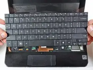
    • Lift the keyboard out of the upper case, minding the cable that is still connecting it to the motherboard.

  6. woVOIZ2EPPHDuGQm
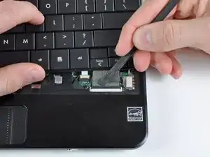
    • Use your fingernail or the flat end of a spudger to flip up the retaining flap on the keyboard cable ZIF socket.

    • Be sure you are prying up on the retaining flap, not the socket itself.

    • Pull the cable out of its socket and remove the keyboard.

  7. bCBDYQNGM1DSQHAM
    bCBDYQNGM1DSQHAM
    xJYleAHmXqoq2bRe
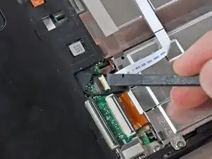
    • Use your fingernail or the flat end of a spudger to flip up the retaining flap on the SIM card ribbon cable ZIF socket.

    • Be sure you are prying up on the retaining flap, not the socket itself.

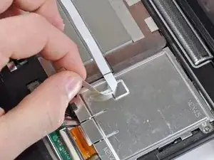
    • Pull the SIM card ribbon cable out of its socket and peel it off the top of the hard drive enclosure.

  8. bnoD5nCjJKW2JOJU
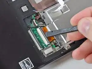
    • Use your fingernail or the flat end of a spudger to flip up the retaining flap on the hard drive cable ZIF socket.

    • Be sure you are prying up on the retaining flap, not the socket itself.

  9. GcNA1u4oW3qE3Lol
    • Remove the two 4.5 mm Phillips screws securing the hard drive to the lower case.

  10. JLvuxSrDOpMxhOdi
    JLvuxSrDOpMxhOdi
    kC6yYhty4iCUXNKa
    • Lift the hard drive up and out of the lower case, being careful not to damage its cable in the process.

  11. sKQ1XkHL3eJ1s6cV
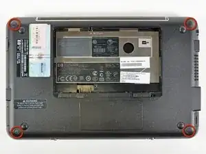
    • Using the sharp tip of a spudger, pry and remove the four plastic screw covers from the underside of the HP Mini 1000.

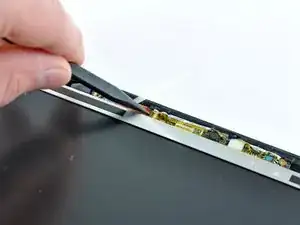
    • There are three different variations of the covers:

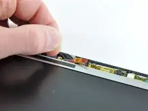
    • The two bottom covers are short in height and are notched to prevent incorrect insertion

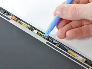
    • The upper right cover is taller in height and is notched.

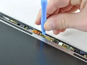
    • The upper left cover is taller in height and is not notched.

  12. ZlGAyuKtNDWPHgel
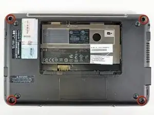
    • Remove the four 7 mm Phillips screws that secure the upper case to the lower case.

  13. ibFHkRXsEnXF6MvW
    • Flip the computer over and open the display.

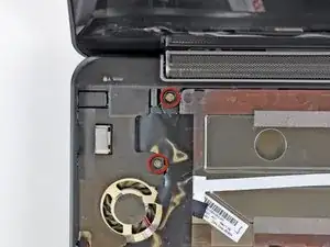
    • Remove the two 4.5 mm Phillips screws securing the upper case to the lower case.

  14. 4yw1ROYW3xYBgmFm
    4yw1ROYW3xYBgmFm
    LisDu44IXIhpBYEW
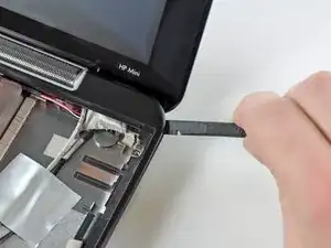
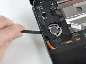
    • Wedge the flat end of a spudger in between the upper case and lower case near the bottom right corner of the display.

    • Carefully pry and rock the spudger upwards to create a small gap between the upper case and lower case.

    • Continue the previously described motion along the right edge of the upper case to release the clips securing the upper case to the lower case.

  15. WbrPAJbbgSdDQ6BU
    WbrPAJbbgSdDQ6BU
    3wOkNBhQNLmrGIBE
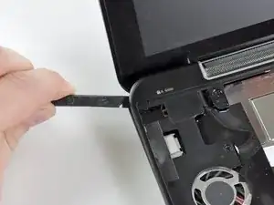
    • Repeat the same procedure as mentioned in the previous step to release the clips along the left side of the upper case.

  16. qyNTGyTYFNSGRgdy
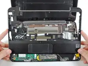
    • Grasp the upper case and carefully lift it slightly upwards, freeing it from any remaining clips.

    • The upper case is still attached via the TouchPad ribbon cable that is connected to the motherboard. Do not remove it completely just yet.

  17. 1jWBHDPfTBanircH
    • Lay the upper case on top of the upper portion of the motherboard.

    • Use your fingernail or the flat end of a spudger to flip up the retaining flap on the TouchPad cable ZIF socket.

    • Be sure you are prying up on the retaining flap, not the socket itself.

    • Pull the TouchPad ribbon cable out of its socket.

    • Remove the upper case from the HP Mini 1000.

  18. bHFkSGaWqHLhDJpm
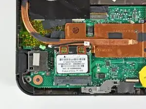
    • If present, peel the sticker up off the top of the Wi-Fi board to reveal the Wi-Fi antenna connectors.

  19. SotnKalk1Wx4dkQf
    SotnKalk1Wx4dkQf
    JIBkZERGtgDTaRUs
    JRxWj2dBPjDjCuhw
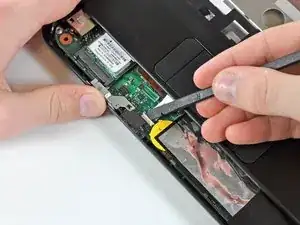
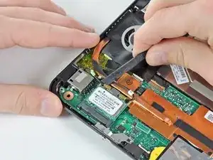
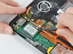
    • Pry the Wi-Fi antenna connectors (2 total) up off the Wi-Fi board.

    • During reassembly, remember to correctly connect the antenna cables to their respective terminals. The green labeled antenna is connected to the "MAIN" terminal and the white labeled antenna is connected to the "AUX" terminal.

  20. YwBQTuAqfrGQqXME
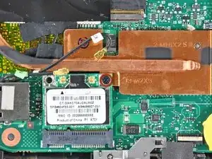
    • Remove the single 3 mm Phillips screw securing Wi-Fi board to the motherboard.

  21. i5Q3DKghC2wKhvTh
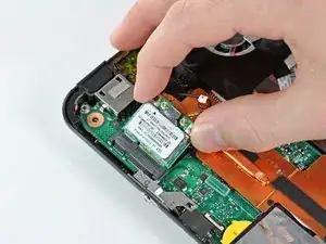
    • Upon removing the Phillips screw that secures the Wi-Fi board to the motherboard, the Wi-Fi board should pop up from its top side nearest the antenna sockets.

    • Grasp the Wi-Fi board and lift it straight away from its socket on the motherboard.

  22. yHK1NF2h12kEYlDm
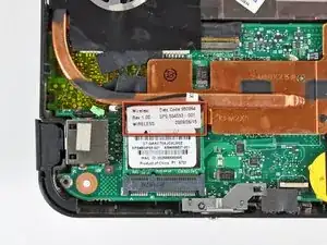
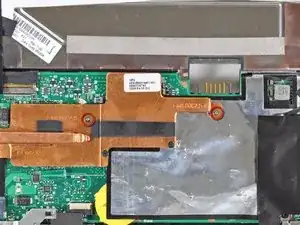
    • Remove the two 2.5 mm Phillips screws securing the heat sink to the motherboard.

    A magnetic Philips #0 makes this much easier to reassemble than non-magnetic.

    Matthew -

  23. 5JRfD1TlFKnywZsn
    5JRfD1TlFKnywZsn
    bERY3JkqPxOOIoQ1
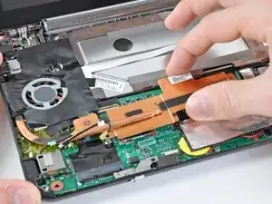
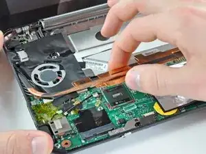
    • Carefully lift the heat sink off the face of the motherboard and de-route the curved section from next to the fan.

    • Before reinstalling the heat sink, be sure to apply a new layer of thermal paste to the CPU. We have a thermal paste guide that makes it easy.

    • Only apply a new layer of thermal paste to the face of the CPU. The CPU is the large processor located closest to the fan.

    This reassembly needs to precede the installation of the the plastic that covers the fan.

    Matthew -

  24. CDxibkwdZbvckfCr
    CDxibkwdZbvckfCr
    vLFStKKOZ3XpOOP1
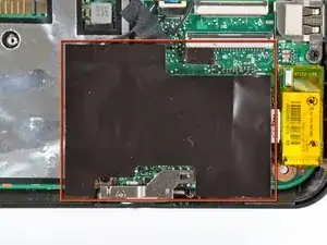
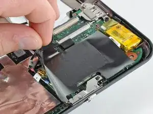
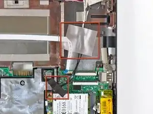
    • If present, carefully remove the large piece of black adhesive film covering the Wi-Fi board.

  25. DnpAFnQJuS2NiC3J
    DnpAFnQJuS2NiC3J
    DIMaeisK1ECXAm5m
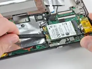
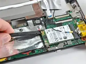
    • Use the flat end of a spudger to pry both antenna connectors up from their sockets on the Wi-Fi board.

  26. meMmAHQNsKnQKBAi
    • If present, remove the pieces of tape securing the Wi-Fi antenna cables to the upper case.

  27. OY2hJBwEXSLdPNgM
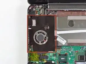
    • If present, carefully remove the large piece of black adhesive film from the area surrounding the fan.

  28. mUUCJuXGEUq1GQFV
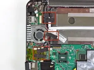
    • If present, remove the several pieces of black cloth tape securing the cables to the upper case near the fan.

  29. 6lGGo2Vbq62ibn1l
    6lGGo2Vbq62ibn1l
    xZeNQ45p55UsnYsj
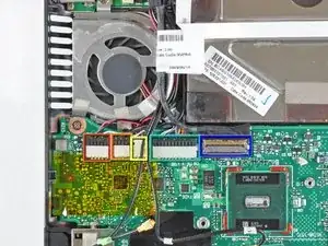
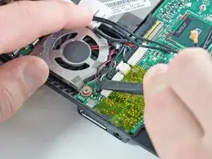
    • Use the flat end of a spudger to disconnect each of the following connectors from their respective sockets:

    • Speaker cable

    • Microphone cable

    • Fan cable

    • Power cable

    • Display data cable

    • Push the connectors out of their sockets parallel to the face of the motherboard toward the display assembly. Do not lift up on the cables as you disconnect them, especially the display data cable, as their sockets may break off the motherboard.

  30. lYxjdKlZNwAyBIEc
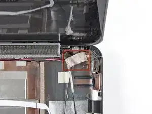
    • If present, peel back the strip of white cloth tape highlighted in red to reveal a display screw.

  31. PRBQtydDNJDNCyYf
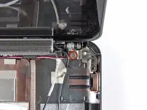
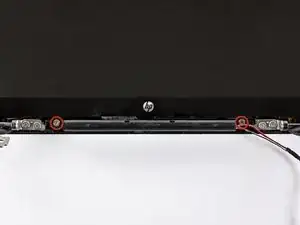
    • Remove the single 5 mm Phillips screw securing the right display hinge to the lower case.

  32. UKFMHNiwVAoQlFE6
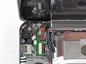
    • Remove the two 5 mm Phillips screws securing the left display hinge to the lower case.

  33. TpNNVEJhH3aDZeLR
    TpNNVEJhH3aDZeLR
    Yi2dfrmhHgGSOvRe
    • Lift the display out of the lower case, minding any cables that may get caught.

  34. fEKCiT1XaB2lNgKm
    fEKCiT1XaB2lNgKm
    Ug2p6fAfD3kAGug2
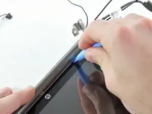
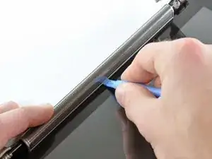
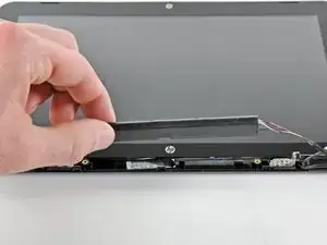
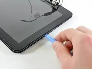
    • Use the edge of a plastic opening tool to pry the left side of the speaker grill away from the display assembly.

    • Be careful not to apply too much pressure to the display glass.

  35. iiS3pDCtuo41prMF
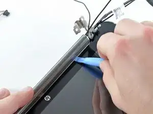
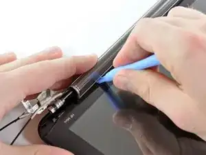
    • Continue prying along the center of the speaker grill.

  36. jajEuByQDG42IOpx
    jajEuByQDG42IOpx
    cUvAlF3RObefdoXG
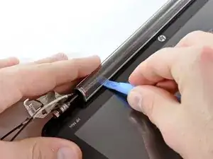
    • Pry the right side of the speaker grill away from the display assembly.

  37. MvDMkcd5SdGECwGq
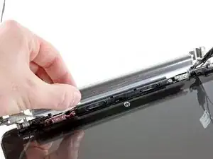
    • Remove the speaker grill.

  38. yvDl2wgxGg4c2oUd
    yvDl2wgxGg4c2oUd
    pZNmFjG5i5YeLPwR
    • Remove the two 4.5 mm Phillips screws securing the speaker assembly to the display.

    • Remove the speaker assembly.

  39. L3vEMwsrvORj5WN5
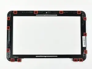
    • In the following steps you will pry the front display bezel off the rear section of the display. The locations of the retaining clips are highlighted in red.

  40. wvuNNLp4TtELI3EW
    wvuNNLp4TtELI3EW
    lgKAsGJENlDPMAYA
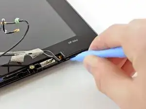
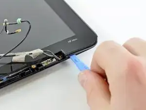
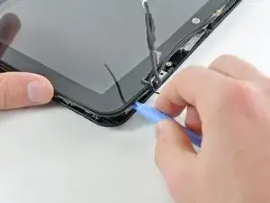
    • Use the edge of a plastic opening tool to pry up the front display bezel near the right display hinge.

  41. 4wNdJoymhaJ2mlQW
    4wNdJoymhaJ2mlQW
    oHiN1niRVEe2Kih5
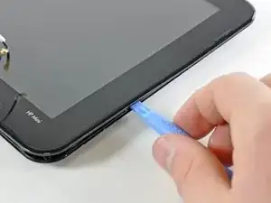
    • Continue prying to release the clips attaching the front display bezel to the right side of the display's rear section.

  42. FZjgO5JjgZBxLZaF
    FZjgO5JjgZBxLZaF
    X3lcVFvOZJYDA2mp
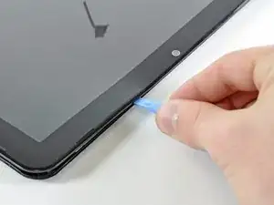
    • Continue prying up the front display bezel along the top edge of the display.

  43. xF5RZIuYtPteLYeo
    xF5RZIuYtPteLYeo
    3URPkFmYBaxqdQbQ
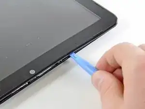
    • Finally, use a plastic opening tool to release the retaining clips along the left side and bottom left corner of the display.

  44. fjV1HKHehmYDWYSP
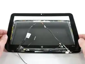
    • Remove the front display bezel from the rest of the display assembly.

  45. QL2iFFXLjEvnVvVO
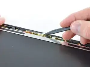
    • Use the sharp end of a spudger to flip up the plastic flap that rests on top of the camera board cable ZIF socket.

  46. M5ulVSII3QTEuTAB
    M5ulVSII3QTEuTAB
    RPrjuNXQXI4nTshi
    • Use your fingernail or the sharp end of a spudger to flip up the retaining flap on the camera board cable ZIF socket.

    • Be sure you are prying up on the retaining flap, not the socket itself.

    • Pull the camera board ribbon cable out of its socket.

  47. LlQKUq242ForyUou
    LlQKUq242ForyUou
    A4TNAcX6QEjpVnaU
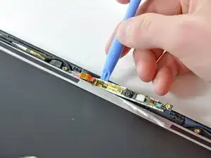
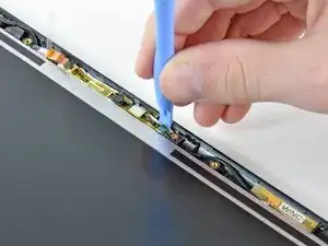
    • Use the edge of a plastic opening tool to pry the right side of the camera board away from the display assembly.

  48. pAKFfQhoBAThWp3G
    pAKFfQhoBAThWp3G
    esZHFbSMxeIhCU4l
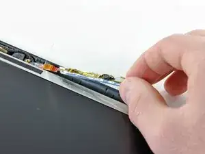
    • Pry the left side of the camera board away from the display assembly.

  49. TfINYETVlFjYpARA
    • Remove the camera board.

Conclusion

To reassemble your device, follow these instructions in reverse order.
Walter Galan

694047 Reputation

0 comments