Introduction
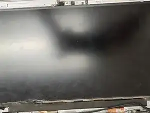
Is your HP EliteBook Folio 1020 G1 screen not turning on, or the display is shattered? If so, here is a guide to fix the problem by replacing the faulty display.
Before taking any part of the computer apart, please remember to power down your computer and unplug the power cable from any power source. Failure to do so could harm yourself or the computer, so these precautions must be taken. Also, when replacing a screen display, there is a chance that the glass could shatter. Please take precautions for the glass.
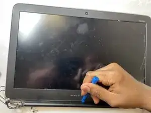
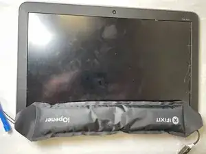
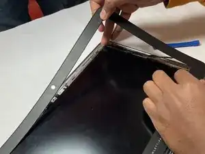
In order to remove the bezel from the display, the iOpener tool is used. To learn how to use the iOpener, follow the instructions here: iOpener Instructions.
Tools
Parts
-
-
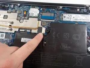
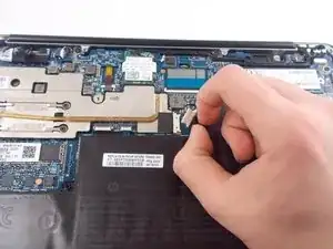
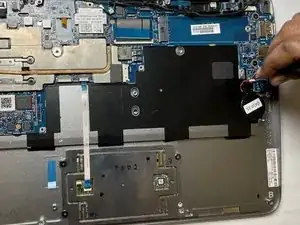
Gently pull and free the battery's bundled cable connector that leads from the battery to the motherboard.
-
-
-
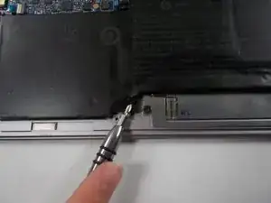
Use a Phillips #1 screwdriver to unscrew and remove the six 4 mm screws that secure the battery.
-
-
-
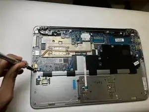
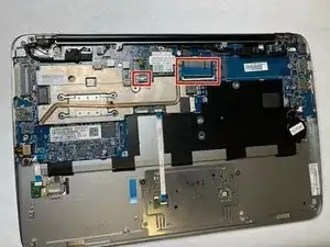
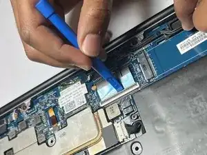
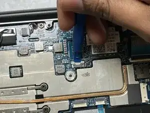
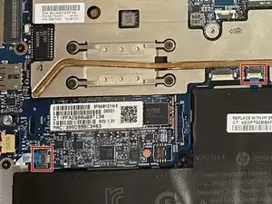
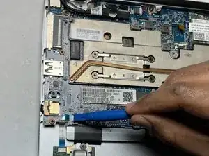
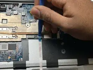
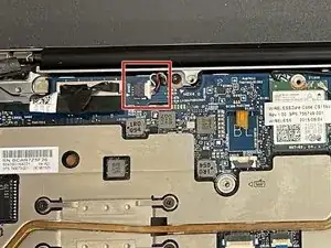
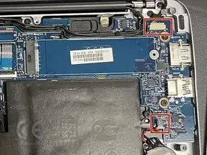
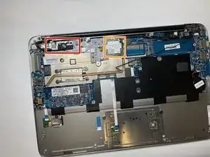
Disconnect circled terminals. Disconnect by lifting the underside of white tabs with spudger.
-
-
-
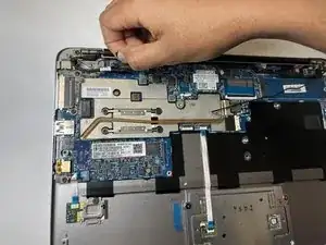
Remove the circled tabs by pulling on the white support edges backward with a pair of tweezers.
-
-
-
Gently pull on the black pull tab on the top of the connector.
-
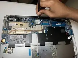
For the wires going to the Wi-fi card, remove both wires going to the top of the card using the tweezers.
-
-
-
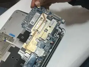
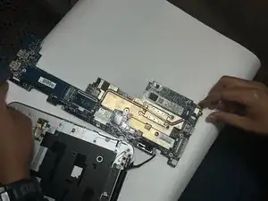
Lift the now disconnected motherboard from the side shown in image 1. This side must be lifted to not damage the ports. The disconnected motherboard (aside from port removed in step 12) is shown in image 2.
-
-
-
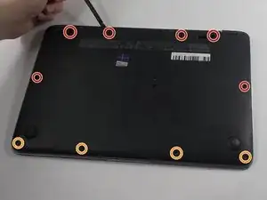
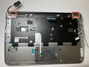
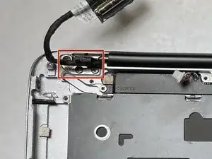
To release the display frame from the lower frame, remove:
-
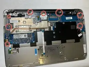
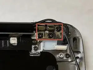
Six 4.1 mm screws using Phillips #0.
-
-
-
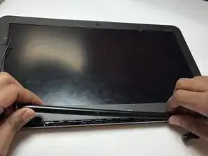
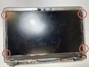
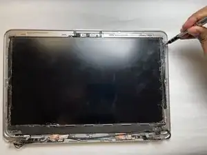
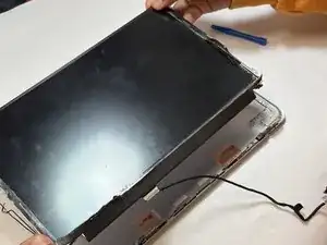
Once the screen is separated from the bottom frame, use a plastic opening tool to remove the bottom trim from the screen.
-
To reassemble your device, follow these instructions in reverse order.
