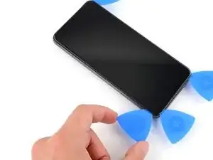
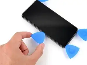
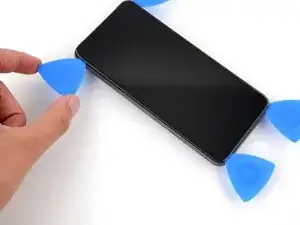
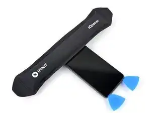
Introduction

This repair guide was authored by the iFixit staff and hasn’t been endorsed by Google. Learn more about our repair guides here.

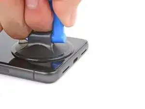
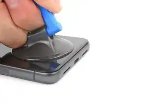
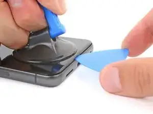
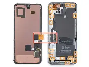
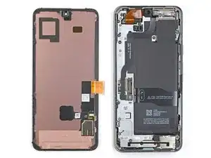
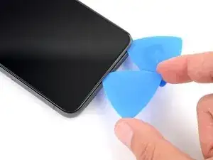
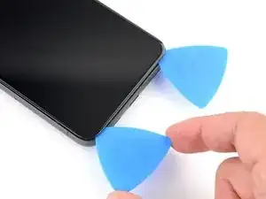
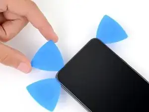
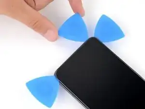
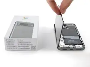
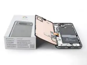
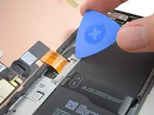
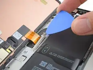
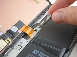
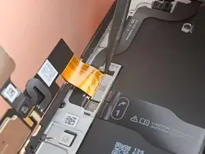
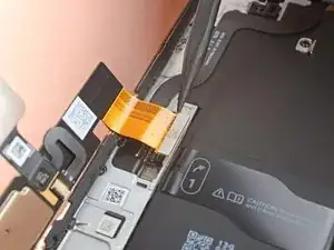
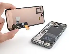
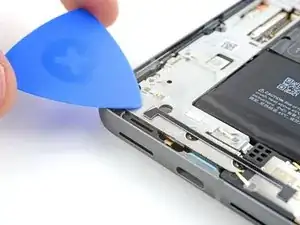
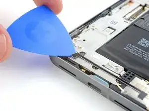
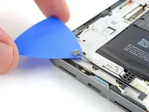
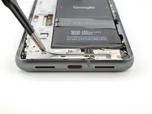
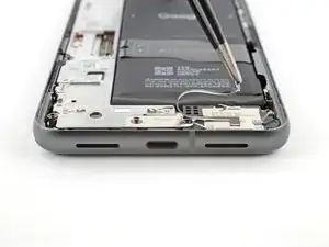
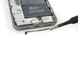
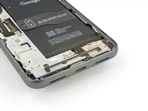
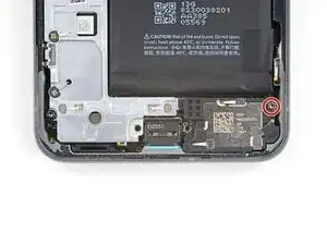
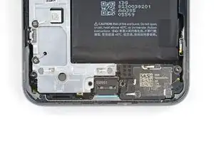
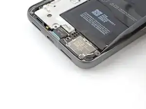
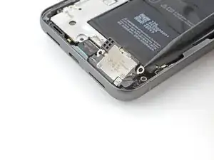
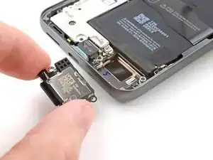
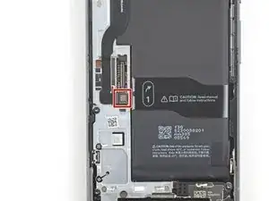
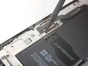
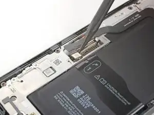
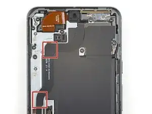
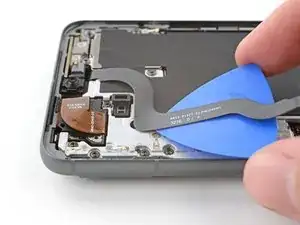
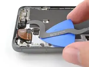
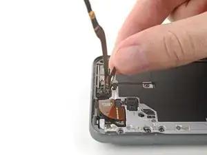
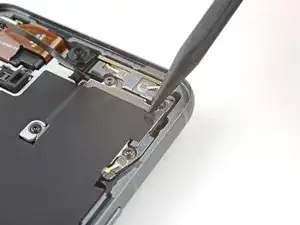
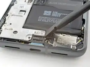
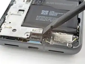
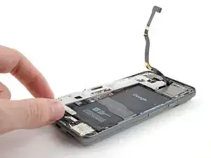
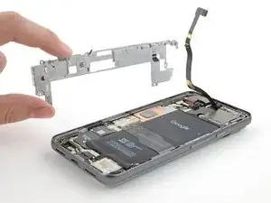
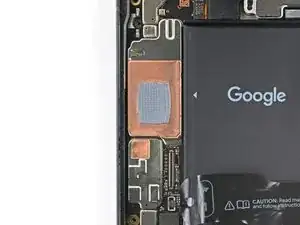
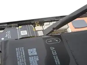
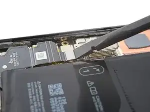
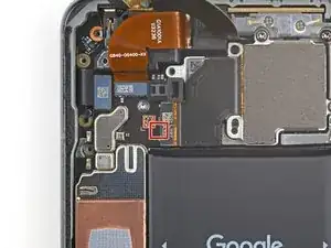
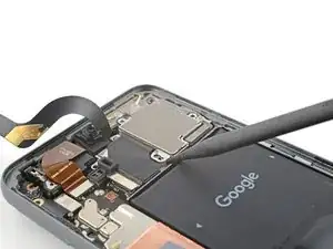
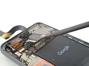
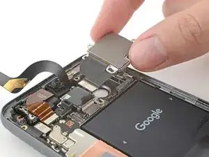
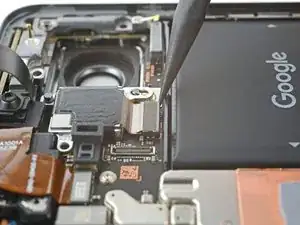
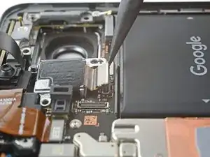
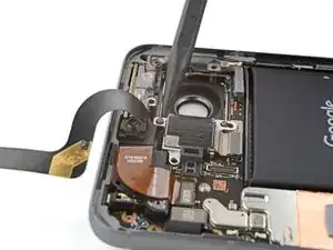
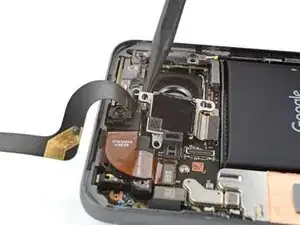
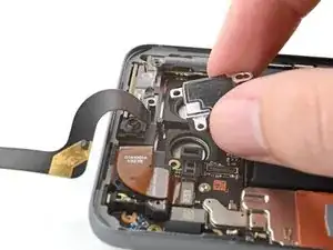
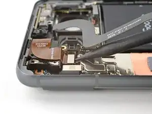
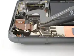
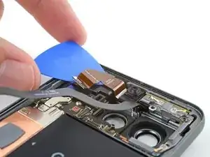
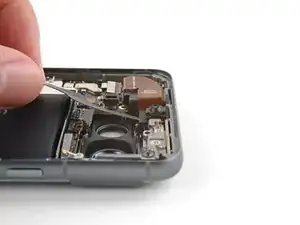
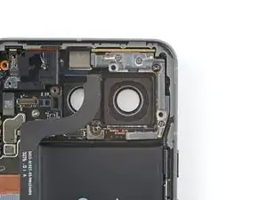
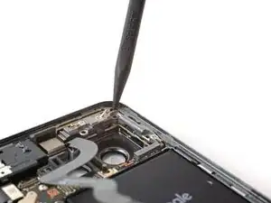
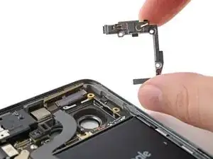
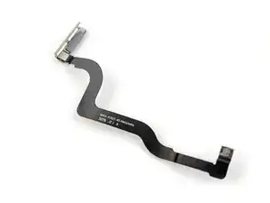
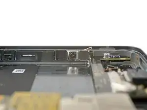
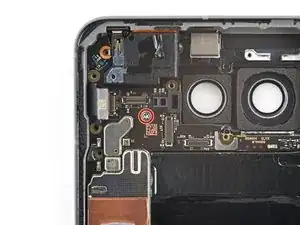
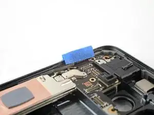
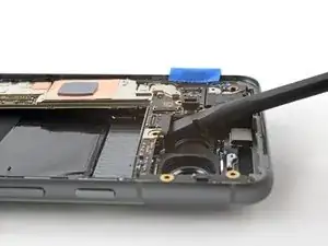
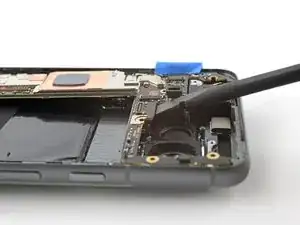
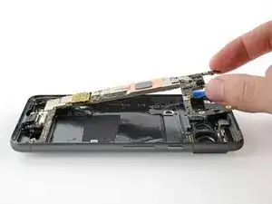
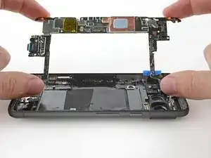
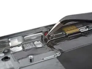
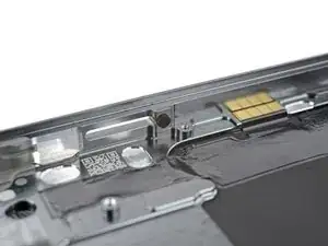
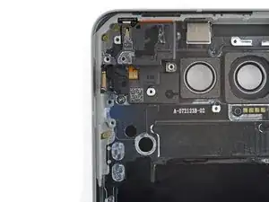
Use this guide to replace the earpiece speaker in your Google Pixel 8.

If phone call sound is muffled or there's no sound at all, it might be time to replace the earpiece speaker.

The earpiece speaker is tucked under the logic board and requires a lengthy disassembly of removing both the logic board and the battery to access the speaker.

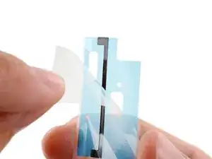
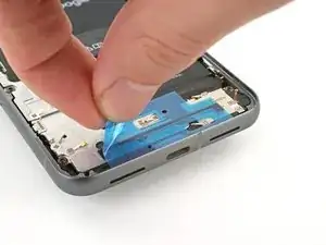
You'll need replacement adhesive to complete this repair.

Note: This guide was made with the 5G mmWave antenna model of the Pixel 8. If you have the non-mmWave version, you can still use this guide—just skip the steps that mention the 5G mmWave antenna.

  1. 3JEVETmFcPY3bGJu
    3JEVETmFcPY3bGJu
    GvrKPSHTYM5FRY5W
    eviZ1n3shxbBWsf1
    • Let your Pixel's battery drain below 25% before starting this repair. A charged lithium‑ion battery may catch fire if damaged.

    • Unplug all cables from your phone.

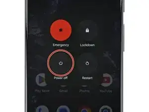
    • Completely power off your phone.

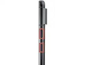
    • Press the power and volume up buttons at the same time to bring up the shutdown menu.

  2. yhCnNhX3ocQiQght
    yhCnNhX3ocQiQght
    RknKYUaPjRRYqDBs
    3foNIDDKR53LYVNH
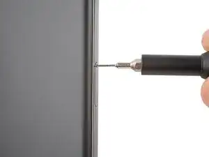
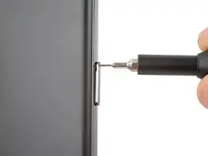
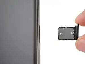
    • Firmly press a SIM eject tool, bit, or straightened paper clip into the SIM card tray hole on the left edge of your phone until the tray ejects.

    • Remove the SIM card tray.

  3. kVvKPHvJUBHgJf1V
    kVvKPHvJUBHgJf1V
    s1NZnrXCN4tM4PwJ
    oVQ2SkCmpqFFu5sV
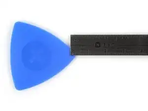
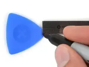
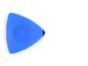
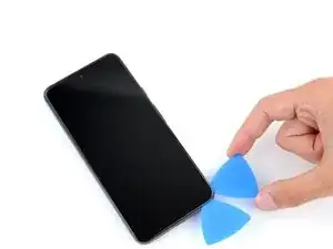
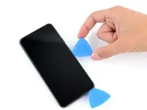
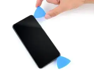
    • You'll be using opening picks to separate the screen from the frame. If inserted too far, a pick can damage your device. Follow this step to mark your pick and prevent damage.

    • Measure 3 mm from the tip and mark the opening pick with a permanent marker.

    • Alternatively, tape a coin to a pick 3 mm from the tip.

  4. lpSmlRZ1dk11liqU
    • Adhesive and clips secure the screen to the frame. Heating the screen softens the adhesive, making it easier to separate.

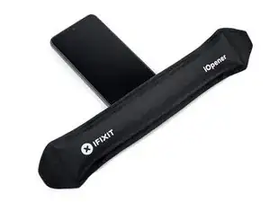
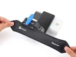
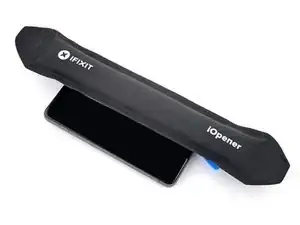
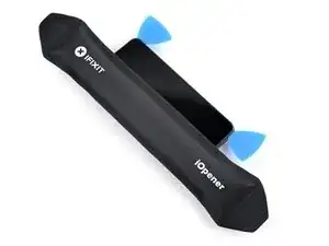
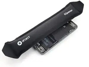
    • Heat an iOpener and lay it on the bottom edge of the screen for two minutes to soften the adhesive.

    • Alternatively, you can use a hair dryer, heat gun, or hot plate—but be careful as extreme heat can damage the screen and/or battery.

    Ich habe gerade sehr gute Erfahrungen mit einer schlichten "nackten" Wärmflasche mit fast kochendem Wasser gemacht. Handy mit dem Display drauf, ein Handtuch drüber, 1-2 Minuten warten, und los geht's. Es wird gleichmäßig erwärmt und keine Gefahr der Überhitzung.

    Paul Sommer -

  5. U3Am65ELWX2EQMIP
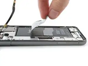
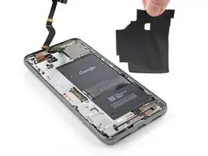
    U3Am65ELWX2EQMIP
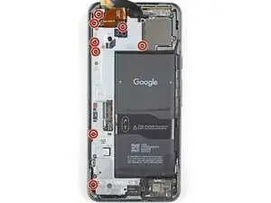
    BKW1njUUkSgZQi1D
    qsCl4Q2af6q1N2IU
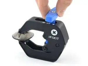
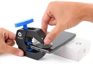
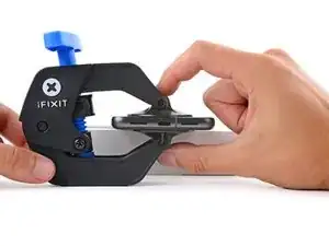
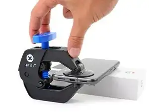
    • The next three steps demonstrate the Anti-Clamp, a tool we designed to make the opening procedure easier. If you aren't using the Anti-Clamp, skip down three steps for an alternate method.

    • For complete instructions on how to use the Anti-Clamp, check out this guide.

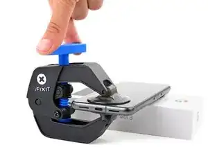
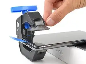
    • Pull the blue handle backwards to unlock the Anti-Clamp's arms.

    • Place your phone screen side up on an object so it will rest level between the Anti-Clamp's arms—the bottom edge should be hanging off.

    • Slide the arms over the left edge of your phone, so you have access to the bottom edge.

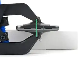
    • Position the suction cups as close to the center of the bottom edge as possible.

    • Squeeze the cups together to create suction.

  6. RPwDEVmDZOCrEdUP
    RPwDEVmDZOCrEdUP
    UUHHZwV3KsQnVZQD
    D2AGi6djFRWgvyYd
    • Pull the handle forward to lock the arms.

    • Turn the handle clockwise one full turn (360 degrees), or until the suction cups begin to stretch.

    • As the cups stretch, make sure they stay aligned with each other. If they keep slipping, remove the Anti-Clamp and apply tape for the cups to stick to.

  7. mOES3S1flJKUdmpv
    mOES3S1flJKUdmpv
    WblG1XpYIKfeDj1J
    3mxHNqFCIIGVywq2
    • Wait one minute for a gap to form between the screen and frame.

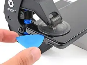
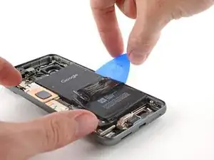
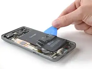
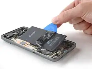
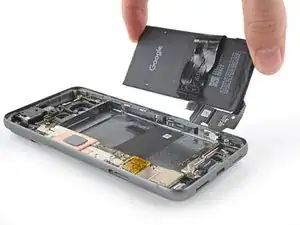
    • If the adhesive doesn't separate, twist the handle clockwise one quarter turn and wait another minute. Apply more heat if the screen cools down.

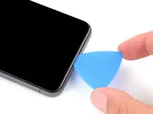
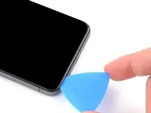
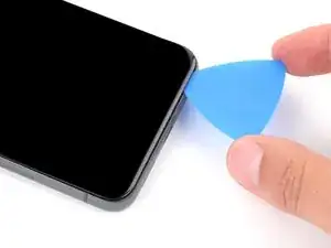
    • Insert an opening pick into the gap.

    • Don't insert your opening pick more than 3 mm to avoid damaging the spring contacts.

    • Pull the blue handle backwards to unlock the arms and remove the Anti-Clamp using the pull tabs on the suction cups.

    • Skip the next two steps

  8. 4rGB4MUDGZCIYDHq
    4rGB4MUDGZCIYDHq
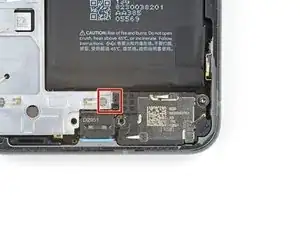
    TjGAFUjbi4chcrcN
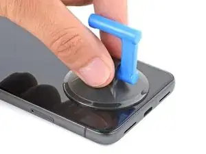
    • Apply a suction handle to the center of the screen's bottom edge.

  9. sGRYcmwagW1IreqC
    sGRYcmwagW1IreqC
    Q5eE2VAXpQB5yEU2
    cNPAjCaFVArHUhIM
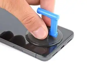
    • Pull up on the suction handle with strong, steady force until a gap forms between the screen and frame.

    • If you're having trouble creating a gap, apply more heat and try again.

    • Insert an opening pick into the gap.

  10. UyQOCnvwMa6j6CrR
    UyQOCnvwMa6j6CrR
    EWK3bMNtbZc33VsS
    • To avoid damaging your phone, don't insert your pick more than 3 mm as you separate the screen adhesive. Note the following areas:

    • The screen cable is a little less than halfway up the left edge of the phone. Be very careful here to avoid tearing the cable.

    • There are many spring contacts around the perimeter of the phone. Be very careful in these areas to avoid bending the contacts.

    I've had 2 devices from Google, both make a creaking snapping noise on the left side of the display above the sim. Clearly it's a design issue and wonder if it could be fixed.

    Jon Kujawa -

  11. wvwjZpTpWJcPvKcP
    wvwjZpTpWJcPvKcP
    ItBg5QBA6YXpHjX3
    UDDRfU2sIfEGQdGh
    • Slide the opening pick along the bottom edge to separate the adhesive securing it.

    • Leave the pick in the bottom right corner to prevent the adhesive from resealing.

  12. 3s414LxtGCmKONGy
    • Apply a heated iOpener to the right edge of the screen for two minutes.

    • Alternatively, you can use a hair dryer, heat gun, or hot plate—but be careful as extreme heat can damage the screen and/or battery.

  13. RDPheHTf3TGOKRvt
    RDPheHTf3TGOKRvt
    euApnDgK5syFFXjB
    YNMnLRZLEcWXXTFT
    • Insert a second opening pick under the bottom right corner of the screen.

    • Slide the new pick to the top right corner to separate the adhesive securing the screen's right edge.

    • Leave the pick in the top right corner to prevent the adhesive from resealing.

  14. CcrU1eUKLeMFbItB
    CcrU1eUKLeMFbItB
    Y1Z6SnVow2ePuyx4
    QSE3rJWKv4Onh1Ns
    • Insert a third opening pick under the bottom edge of the screen.

    • Slide the new pick to the bottom left corner.

    • Leave the pick in the bottom left corner to prevent the adhesive from resealing.

  15. sV1Cju2fthvJaGLL
    • Apply a heated iOpener to the left edge of the screen for two minutes.

    • Alternatively, you can use a hair dryer, heat gun, or hot plate—but be careful as extreme heat can damage the screen and/or battery.

  16. gbYSvq5vngVyLFtY
    gbYSvq5vngVyLFtY
    cjRaPOSRadNaQSht
    pe2DmjdhfHwvco5k
    • Insert a fourth opening pick under the bottom left corner of the screen.

    • Slide the new pick to the top left corner to separate the adhesive securing the screen's left edge.

    • Leave the pick in the top left corner to prevent the adhesive from resealing.

  17. P6XYwnAFUXjIYIcr
    • Apply a heated iOpener to the top edge of the screen for two minutes.

    • Alternatively, you can use a hair dryer, heat gun, or hot plate—but be careful as extreme heat can damage the screen and/or battery.

  18. BLBNFExV4tA5PStJ
    BLBNFExV4tA5PStJ
    X2LTiwZwusdN3tLp
    • Insert a fifth opening pick under the top edge of the screen, near the left corner.

    • Slide the opening pick to the top right corner to separate the adhesive securing the screen's top edge.

  19. rLDvlCwEF5GuNXBB
    rLDvlCwEF5GuNXBB
    CdEvOHmoVBWYPAyc
    • Place a small box or stack of books to the left of your phone so you can prop up the screen while disconnecting its cable.

    • Swing up the right edge of the screen like the front cover of a book.

    • Be careful not to strain the screen cable.

    • If the screen feels stuck, go back around the perimeter with an opening pick to separate any remaining adhesive.

    • Prop up the screen so you can access the screen cable.

  20. ugBQvxJtRsJhyUGW
    ugBQvxJtRsJhyUGW
    Ji4MNoJVtFKGUvHV
    LUnESjmbtcvSwZ3s
    • Use an opening pick to pry up the upper edge of the screen cable cover.

    • Remove the cover.

  21. VjtC6xPBuYhgRx6i
    VjtC6xPBuYhgRx6i
    LgGAdhGPjEROZKxw
    • Insert the point of a spudger under the top left corner of the screen's press connector.

    • Gently pry up and disconnect the cable.

    • To re-attach press connectors, carefully align and press down on one side until it clicks into place, then repeat on the other side. Don't press down in the middle. If the connector is misaligned, the pins can bend and cause permanent damage.

  22. Hd2uyviYR2BoeTiU
    • Remove the screen.

    • During reassembly:

    • If you replaced your screen, check the front-facing camera hole on your replacement screen and remove any remaining liners.

    • Remember to reinstall the screen cable cover.

    • This is a good point to test your phone before sealing it up. Temporarily connect your screen, power on your phone, and make sure it works as expected. Before continuing with reassembly, power off your phone and disconnect the screen.

    • Follow this guide to replace your screen adhesive.

    • If you're installing a new screen, follow this guide to calibrate the fingerprint sensor.

  23. rhIJKco4BSeUalJx
    rhIJKco4BSeUalJx
    naDfVXbRZqNsH5qm
    guFxGrHE32oZPVwx
    • A plastic buffer is lightly adhered to the midframe and bottom speaker.

    • Slide the tip of an opening pick under the plastic buffer until you can grip it with tweezers or your fingers.

  24. fKjfpeU6TffGObsO
    fKjfpeU6TffGObsO
    vJ4WusoKESiOCFF1
    VRwedTgNs4r6Kd6o
    • Use tweezers, or your fingers, to peel off and remove the plastic buffer from the midframe and the bottom speaker.

  25. US5Cl6MAOrkFaSAU
    US5Cl6MAOrkFaSAU
    vKBNeGsYYvwXoIHV
    • Throughout this repair, keep track of each screw and make sure it goes back exactly where it came from.

    • While the Pixel 8 uses Torx Plus screws, standard Torx bits will also work. Make sure to apply constant, downward force to prevent stripping.

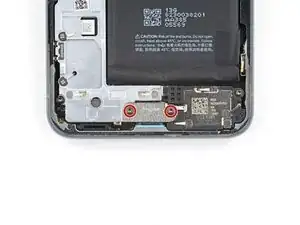
    • Use a T3 Torx driver to remove the two 5 mm‑long 3IP Torx Plus screws securing the USB‑C port bracket.

  26. IP1cVrfehaeBoSnT
    IP1cVrfehaeBoSnT
    DGLvpOWKeLSKnEra
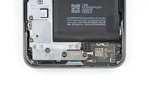
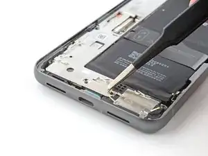
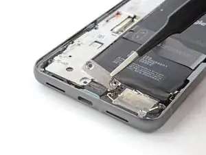
    • Use tweezers, or your fingers, to remove the USB-C port bracket.

  27. 1SZGNZMFMOCtsXpw
    1SZGNZMFMOCtsXpw
    h6pUd4RGxn3xEiVT
    Ap6J5NLZ2PrrbQ2v
    • During reassembly, follow this step to replace the plastic shim that runs across the bottom of the midframe and loudspeaker. If you don't have a replacement, press the old one back into place.

    • Remove the clear liner from the shim.

    • Use the markings on the midframe to align the left side of the shim and press it into place.

    • Use the flat end of a spudger to firmly press down along the whole shim to secure it.

    • Remove the blue liner.

  28. jRJFVKQuD1mdCiPX
    jRJFVKQuD1mdCiPX
    IfdfDkeXnxA1ZHvP
    • Use a T3 Torx driver to remove the 5 mm‑long screw securing the bottom speaker.

  29. ZTIk4adjKpjaqplf
    ZTIk4adjKpjaqplf
    CXrRLH4CWZtVcfKx
    fMCnu3QNQ263MqBU
    • Insert the point of a spudger between the top right corner of the bottom speaker and the frame.

    • Pry the bottom speaker up with the spudger to dislodge it from its recess.

    • Remove the bottom speaker.

    • During reassembly, insert the edge of the speaker with an black gasket at a downward angle into its recess. Then press the speaker firmly into place.

  30. EKekGuYVgGAUcF3T
    EKekGuYVgGAUcF3T
    foHeOYUTra4KFhyZ
    XCAvRXHeO3ikPkVN
    • Use the point of the spudger to pry up and disconnect the 5G mmWave antenna cable from the logic board.

  31. WXDMxosEetlZPHNN
    WXDMxosEetlZPHNN
    SMQ3XMNYJdbolSqs
    • The 5G mmWave antenna cable is secured to the midframe with adhesive in two places.

    • Heat an iOpener and lay it on the left edge of the phone for two minutes to soften the cable adhesive.

    • Alternatively, you can use a hair dryer, heat gun, or hot plate—but be careful as, extreme heat can damage the battery.

  32. lLJMjTtrBLOcO4ag
    lLJMjTtrBLOcO4ag
    sReDRsNRDkZgWuFI
    xjGtU1lsOHMWpP2j
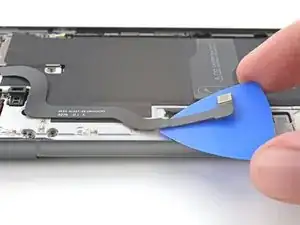
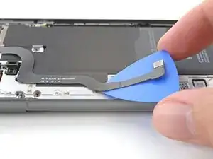
    • Insert an opening pick under the 5G mmWave antenna cable's bottom section of adhesive.

    • Slide the pick toward the top edge of the phone to separate the adhesive.

  33. 12k1rKhqSpACLZqL
    12k1rKhqSpACLZqL
    IXAQe2gKPEWSNiRt
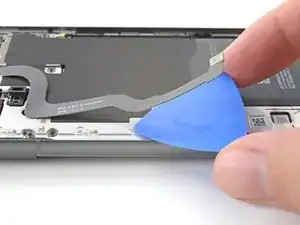
    • Repeat the previous step for the upper section of adhesive.

  34. oqqTVKTkWhQERMjy
    • Move the 5G mmWave antenna cable over the top of the phone to keep it out of the way.

    • Don't fold or crease the cable—just move it enough so it doesn't interfere with disassembly.

  35. wZrmLYs2SF1QCatt
    wZrmLYs2SF1QCatt
    LeZVscuEEAnfamlX
    jSTesJpAeGjT2Uhu
    • A large graphite sheet must be removed and replaced to complete this repair. It connects the upper part of the battery, midframe, and the rear cameras.

    • Insert the point of a spudger under the top right corner of the graphite sheet and lift until you can grip the sheet with your fingers.

    • Peel up and remove the entire graphite sheet.

    • If your sheet tears, don't worry! Grip the torn parts and remove the sheet in sections.

    • During reassembly, do not reuse the old graphite sheet. Follow this guide to replace the sheet.

  36. jLXmDyNCntfhYJAt
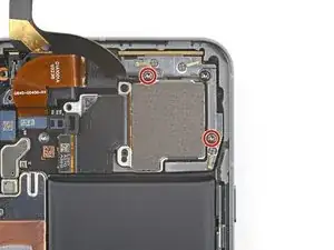
    • Use a T3 Torx screwdriver to remove the eight 5.1 mm‑long 3IP Torx Plus screws securing the midframe.

  37. hVXCWtOTQJ5Fkp6o
    hVXCWtOTQJ5Fkp6o
    kdf4DJwllb5BiTLP
    txhHsWwSYDPTHNPi
    • The center of the midframe is lightly bonded to a thermal pad.

    • Slide the flat end of a spudger under the bottom right corner of the midframe to separate it from the thermal pad.

    • You'll feel the midframe loosen once it separates completely.

  38. GG1PUvZlm4nhvXks
    GG1PUvZlm4nhvXks
    ZDv4UZiNTZkdcIre
    16bqpqumySrxrg6U
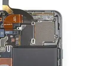
    • Lift the midframe off the frame and remove it.

    • During reassembly check the condition of the thermal pad. If it's damaged, remove the pad, clean the area with high-concentration (greater than 90%) isopropyl alcohol and a microfiber or lint-free cloth, and apply a new thermal pad.

  39. ok42BgvrBKnNBYVQ
    ok42BgvrBKnNBYVQ
    ST5bMkvBANKPNXUA
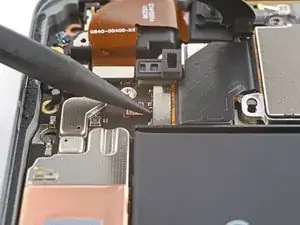
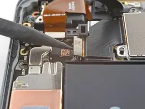
    • Use a spudger to pry up and disconnect the battery connector.

  40. o6OiZP2NeTLHyZ1c
    o6OiZP2NeTLHyZ1c
    YMHZXViuh31JyXNM
    QfLSRIO2KAEKK3pF
    • Insert the point of a spudger under the bottom half of the wide rear camera press connector, between the surface-mounted components.

    • Don't insert your pick anywhere else, as you risk damaging the logic board.

    • Pry up to disconnect the wide rear camera.

  41. QSRFdDXZ4WlkoKUS
    QSRFdDXZ4WlkoKUS
    pSYEC4MdVFRGnjqI
    • Use a T3 Torx screwdriver to remove the two 5.1 mm‑long 3IP Torx Plus screws securing the wide rear camera.

  42. Q6dpJNS5GjrCSoNu
    Q6dpJNS5GjrCSoNu
    tL64HubxssJtR2OV
    IAIVQcSeYGNULRV3
    • Insert the tip of a spudger under one of the wide rear camera screw hole cutouts.

    • Use the spudger to lift the camera out of its recess.

    • Remove the camera.

  43. lEoENGZOrVCYu4BL
    lEoENGZOrVCYu4BL
    GrNRMoVTruZsEcVD
    • Use a spudger to pry up and disconnect the ultrawide rear camera press connector from the logic board.

  44. VuklqPneBb3IgdJX
    VuklqPneBb3IgdJX
    YoGGBn2rG1Lre1uC
    O5db6UeZAHnsxRHJ
    • Insert the tip of a spudger under the top screw cutout on the ultrawide rear camera.

    • Use the spudger to lift the camera out of its recess.

    • Remove the camera.

  45. JWCTVxOcItLO3XAY
    JWCTVxOcItLO3XAY
    CF6qrPdr3vh15M1t
    • Use a spudger to pry up and disconnect the front camera press connector from the logic board.

  46. ePoManWxSEKNe12x
    ePoManWxSEKNe12x
    iMDBdgcMZhO2NmFi
    • The front camera cable is lightly adhered to the earpiece speaker.

    • Slide an opening pick under the front camera cable to separate the adhesive.

    • During reassembly, reuse your old adhesive if it's still sticky. If not, use a double-sided tape like Tesa Tape to resecure the front camera.

  47. qCTkoua5U3EdVZYq
    qCTkoua5U3EdVZYq
    hqlF2vVvJnQ5nHJa
    jw2Xf2xseG4rWsvT
    • The 5G mmWave antenna cable overlaps the bottom edge of the front camera.

    • Move the antenna cable toward the right edge of the phone to free the front camera.

    • Remove the front camera.

    • During reassembly, make sure the front camera rests properly in its recess and under the antenna cable.

  48. e32rqN6vcVopNRkg
    e32rqN6vcVopNRkg
    ecPsdwdIuiHLcVqq
    • Use a T3 Torx screwdriver to remove the 5.1 mm‑long 3IP Torx Plus screw securing the 5G mmWave antenna bracket.

  49. rQLvdASmCSOsuvZO
    rQLvdASmCSOsuvZO
    UJjSVJKQbApyhcEt
    j4NcQScrTUpeYRcU
    • Insert the point of a spudger in the notch at the top right corner of the 5G mmWave antenna bracket.

    • Pry up with the spudger to separate the bracket from its recess in the frame.

    • Remove the bracket.

    • During reassembly, reinsert the top edge of the bracket first at a downward angle so its foam pad sits properly before resecuring the bracket.

  50. eXfHwn2Y5EHkxW2U
    eXfHwn2Y5EHkxW2U
    1joZIgy2xuh2IEUR
    DP1R3hQEMOISvUKv
    • Pull the antenna and its cable out of the frame and remove it.

    • If your cable disconnects from the antenna, don't worry! Align the cable press connector over its socket and press down with your fingers until it snaps into place.

  51. EwUrIEDvIgIwZaMZ
    EwUrIEDvIgIwZaMZ
    D1qDnsb6fECfdFPq
    • Use a spudger to pry up and disconnect the interconnect cable press connector.

  52. rT1c4toNSuyoZ3NC
    • Adhesive secures the top and bottom edges of the battery to the frame. Heating the back cover softens the adhesive, making it easier to separate.

    • Carefully flip your phone over and lay it down on your workspace.

    • Use a hairdryer or heat gun to heat the left side of the back cover, near the top and bottom edges of the battery. It should be slightly too hot to touch.

    • Be careful not to heat the phone hotter than this—the battery is susceptible to heat damage.

  53. ktqcRVCjFvKNmymQ
    ktqcRVCjFvKNmymQ
    5gPcKJKhfYLpeeCB
    • Flip your phone back over and lay it on your workspace.

    • Apply a few drops of highly-concentrated isopropyl alcohol (>90%) along the right edge of the battery.

  54. SME2CTaeb6ZiMP4b
    SME2CTaeb6ZiMP4b
    uMZ1tcFLXKWZJeE1
    • Tilt your phone to help the alcohol flow towards the adhesive on the top and bottom edges of the battery.

    • Wait one minute to allow the alcohol to dissolve the adhesive.

  55. sktCtWM6kxSTBXdi
    sktCtWM6kxSTBXdi
    xxXwUeR3YQWK1Hum
    • Insert the flat side of an opening pick between the right edge of the battery and frame.

  56. EsZ5glTZmKB33R1t
    EsZ5glTZmKB33R1t
    SiQvuMOCr1uGUsRN
    • Don't crease or bend the battery—it can leak dangerous chemicals and/or catch fire.

    • The adhesive securing the battery is very strong. Separating it requires time and constant pressure. It will most likely take multiple rounds of heat and isopropyl alcohol.

    • Firmly secure your phone with one hand.

    • With your free hand, pry the battery up with the pick. Maintain constant pressure on the pick until the battery separates from the frame.

    • If after two minutes of constant pressure the battery doesn't budge, apply more heat and isopropyl alcohol and try again.

  57. olbGPGwooBXZlDpi
    olbGPGwooBXZlDpi
    lhTPJvcVsbwFSIqi
    rYvTAEMxoFsZJGYy
    • If your battery is creased, bent, or deformed, do not reuse it—it's a fire hazard. Replace it with a new battery.

    • Use the opening pick to lift the battery and separate the remaining adhesive.

    • Remove the battery.

    • During reassembly, follow this guide to remove the old adhesive and install your battery.

  58. qRhwdH51bW1OnnRI
    qRhwdH51bW1OnnRI
    MReg4ctF3WTrcNP5
    • Use a T3 Torx screwdriver to remove the 2.5 mm‑long 3IP Torx Plus screw securing the grounding bracket to the bottom right edge of your phone.

  59. tXr3EEtIpmdiP2jv
    tXr3EEtIpmdiP2jv
    gFGWAe3Okhs3RTql
    • Remove the grounding bracket.

  60. tTblq3dOLLhXl52K
    tTblq3dOLLhXl52K
    tulBgQ5pZmWGUh65
    • Use a T3 Torx screwdriver to remove the two 3.5 mm‑long 3IP Torx Plus screws securing the logic board.

  61. UjNPRfTZOXvtbMoL
    UjNPRfTZOXvtbMoL
    MTgmCDxICY4yRYVd
    • Move the interconnect cable away from the frame to keep it from snagging on the logic board.

    • Optionally, you can tape the cable to the left edge of the phone.

  62. 63pDmVmHZKGjUTIi
    63pDmVmHZKGjUTIi
    wXbgFOmOYHWX5GTD
    qyCQG1WaTiJcAcxg
    • Before removing the logic board, make sure the SIM card tray is removed.

    • Use the flat end of a spudger to lift the top edge of the logic board until you can grip it with your fingers.

  63. A2Eb2tGqb2tHrLRX
    A2Eb2tGqb2tHrLRX
    RNXjjckUdI6aNXGp
    tunfFnMibggOmmWH
    • Lift the top of the logic board upward to release its bottom clip.

    • Remove the logic board.

    • During reassembly, reinsert the USB-C port at a downward angle and align the rubber gasket before pressing the logic board into place.

  64. rJMtXBnoU1esYQYd
    rJMtXBnoU1esYQYd
    yvr5LcEucV4BCMps
    • If your rubber plunger next to the SIM card tray slot fell out, reinsert it with the red rings facing the outer edge of the phone.

  65. ECbgXUXBgTcs4vyr
    ECbgXUXBgTcs4vyr
    P11GeqcIL63AF3C2
    • Use a T3 Torx driver to remove the 2.5 mm‑long 3IP Torx Plus screw securing the earpiece speaker.

  66. yASkgGKEHtxTK5bF
    yASkgGKEHtxTK5bF
    uXV64hPkXwZYVCna
    rySRu22L1JADYtud
    • Slide an opening pick under the bottom right corner of the earpiece speaker to separate it from the frame.

    • Remove the earpiece speaker.

Conclusion

To reassemble your device, follow these instructions in reverse order.

To run a diagnostics test with the built-in Pixel Diagnostic tool, click here.

Take your e-waste to an R2 or e-Stewards certified recycler.

Repair didn’t go as planned? Try some basic troubleshooting, or ask our Google Pixel 8 Answers Community for help.
Alex Diaz-Kokaisl

Member since: 16/01/22

117881 Reputation

0 comments