Introduction

This repair guide was authored by the iFixit staff and hasn’t been endorsed by Google. Learn more about our repair guides here.

Follow this guide to remove or replace the wide camera in your Google Pixel 7a.

You might need to replace your wide camera if it doesn't focus or stabilize properly, or if there is physical damage from a cracked or scratched lens.

Note: The Verizon model Google Pixel 7a (G0DZQ) has a 5G mmWave antenna. If you have this model, some photos in this guide differ, but the procedure is the same.

If your battery is swollen, take appropriate precautions.

You'll need replacement adhesive in order to complete this repair.

Note: Any repair can compromise the water resistance of your phone. Retaining water resistance after the repair will depend on how well you reapply the adhesive.

  1. oTvToevuIyEPXQJt
    oTvToevuIyEPXQJt
    DgiJJLhpPrIMBAmo
    • Allow your battery to drain below 25% before starting this repair. A charged lithium-ion battery is a potential safety hazard.

    • Unplug any cables from your phone and fully power it down.

  2. nUiCsKPYXeuMZibI
    nUiCsKPYXeuMZibI
    uurIAeWaNlNrXHWU
    iQYIsRUNADCJva2g
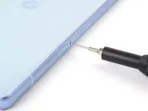
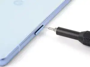
    • Insert a SIM eject tool, bit, or straightened paper clip into the SIM card tray hole.

    • Press the SIM eject tool into the hole to eject the SIM card tray.

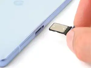
    • Remove the SIM card tray.

  3. cV6nABEAOv1E1h5B
    • Apply a heated iOpener to the bottom edge of the rear cover for three minutes.

    • Alternatively, you can use a hair dryer, heat gun, or hot plate to warm the rear cover.

    • Only heat the phone enough so it's just hot to the touch. Extreme heat can damage the screen, rear cover, or battery.

  4. 2nFrVZPM1Vs5Cw2S
    2nFrVZPM1Vs5Cw2S
    ZaSO3HSB4d15Canr
    LIqICQXRWEg22AXF
    • The next three steps demonstrate the Anti-Clamp, a tool we designed to make the opening procedure easier. If you aren't using the Anti-Clamp, skip down three steps for an alternate method.

    • For complete instructions on how to use the Anti-Clamp, check out this guide.

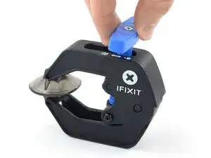
    • Pull the blue handle backward to unlock the Anti-Clamp's arms.

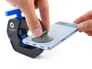
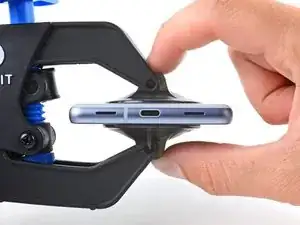
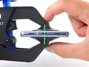
    • Slide the arms over the bottom edge of the phone, with one suction cup on the rear cover and one on the screen.

    • Squeeze the cups together to create suction.

  5. mJxNwDjfRSEj5QCy
    mJxNwDjfRSEj5QCy
    BAmIdyTxLtSQIUQ3
    LuEvLFlAcctEF6Hw
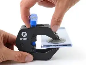
    • Pull the blue handle forward to lock the arms.

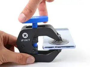
    • Turn the handle clockwise one full turn (360 degrees), or until the suction cups begin to stretch.

    • As the cups stretch, make sure they stay aligned with each other. If they keep slipping, remove the Anti-Clamp and apply tape for the cups to stick to.

  6. u1pcy4CDGbHBhpm2
    • While the heat from an iOpener is sufficient to separate the rear cover, it might cool down while you set up the Anti-Clamp. Reheat the rear cover if you need more time to set it up.

    • Place an object under your phone so it rests level while between the Anti-Clamp's arms.

    • Wait one minute, or until the adhesive separates, for a gap to form along the bottom edge of the phone.

    • Insert an opening pick into the gap between the rear cover and the frame.

    • If the adhesive doesn't separate, twist the handle clockwise one quarter turn and wait another minute. Apply more heat with a hair dryer or heat gun if the rear cover cools down.

    • Remove the suction cups from the phone using their pull-tabs and set the Anti-Clamp aside.

  7. t2aXMNQXyZurQsBd
    t2aXMNQXyZurQsBd
    PWk2UrCggILhfvZC
    Y2GVFAEqwtEqbeXe
    • If you've already inserted an opening pick using the Anti-Clamp, skip this step.

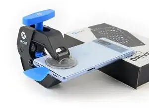
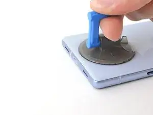
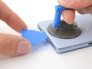
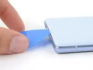
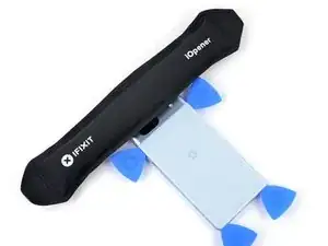
    • Apply a suction handle to the center of the bottom edge of the rear cover.

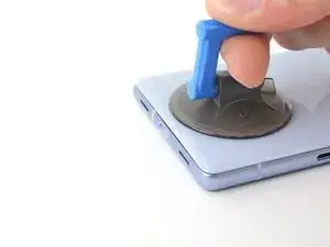
    • Pull up on the suction handle with a strong, steady force until a gap forms between the rear cover and frame.

    • Insert the tip of an opening pick into the gap.

    • Remove the suction handle.

  8. 3NP2iNpt5cXvk1WA
    3NP2iNpt5cXvk1WA
    2RTUKCdHHHUGlBBu
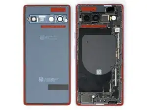
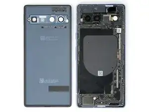
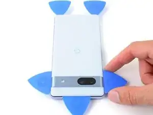
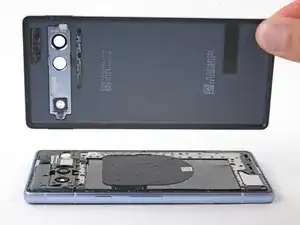
    • The rear cover is secured with adhesive around the perimeter of the frame and near the cameras. Use this picture as a reference while you slice the adhesive.

  9. AQwYAfstUZJttvVH
    AQwYAfstUZJttvVH
    HogKVqwBC5cpUOvQ
    wiwVUXVSDUAomxuB
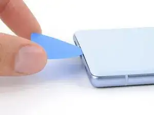
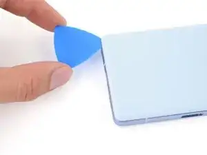
    • Angle the opening pick upward so the tip faces away from the frame.

    • From here on, keep all opening picks angled upward while slicing until the rear cover is fully removed.

    • Slide your pick to the bottom left corner of the rear cover.

    • Leave this pick in place to prevent the adhesive from resealing.

  10. avWfNxrrXPe6kPep
    avWfNxrrXPe6kPep
    TvMqvbhHWjb4GkAc
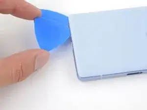
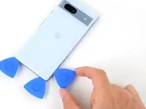
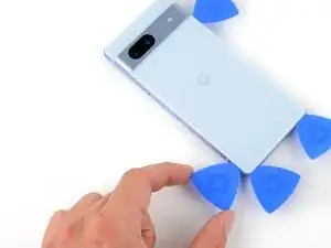
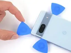
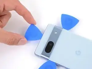
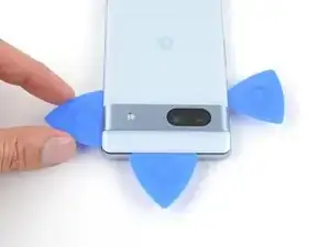
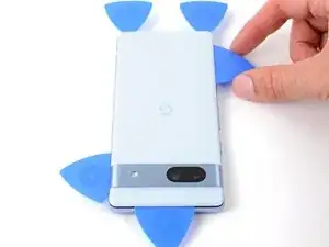
    • Insert a second opening pick in the bottom left corner.

    • Slide the new pick to the bottom right corner of the rear cover to separate the bottom edge adhesive.

    • Leave this pick in place to prevent the adhesive from resealing.

  11. DKlYHQF4LSt6NVel
    • Apply a heated iOpener to the right edge of the rear cover for two minutes.

    • Alternatively, you can use a hair dryer, heat gun, or hot plate to warm the rear cover. Remember to not overheat the phone.

  12. J5QUccAnUJXeCOiX
    J5QUccAnUJXeCOiX
    jSIFhTRHqEpZRCZA
    kMUATS3TefLs6iHj
    • Don't insert your pick deeper than 5 mm along the right edge to avoid damaging the wireless charging coil.

    • For a visual reference, you can measure 5 mm from the tip and mark your pick with a permanent marker.

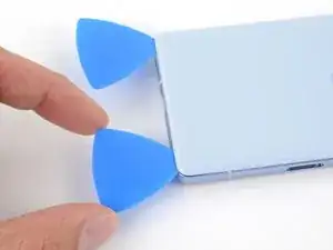
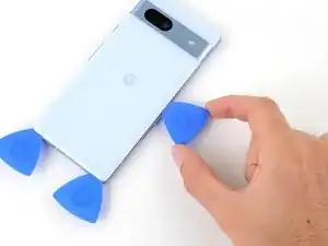
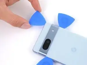
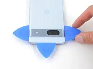
    • Insert a third opening pick in the bottom right corner of the rear cover.

    • Slide your pick up the right edge of the rear cover to separate its adhesive. Stop when you reach the camera bar.

    • Leave this pick in place to prevent the adhesive from resealing.

  13. ic6DqNBw6gEsV4eH
    • Apply a heated iOpener to the left edge of the rear cover for two minutes.

    • Alternatively, you can use a hair dryer, heat gun, or hot plate to warm the rear cover. Remember to not overheat the phone.

  14. XioQJbam3XoK23Jt
    XioQJbam3XoK23Jt
    ln2ImOJPnFy4Bh4n
    yTWprCsR1vm4MZfk
    • Don't insert your pick deeper than 3 mm along the left edge to avoid damaging the wireless charging coil and rear cover foam pad.

    • For a visual reference, you can measure 3 mm from the tip and mark your pick with a permanent marker.

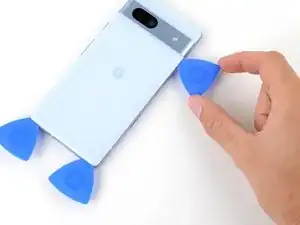
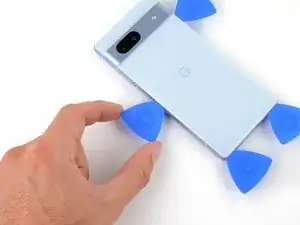
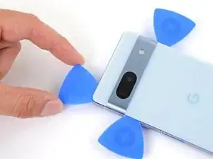
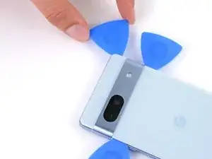
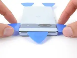
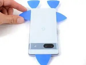
    • Insert a fourth opening pick in the bottom left corner of the rear cover.

    • Slide your pick up the left edge of the rear cover to separate the adhesive. Stop when you reach the camera bar.

    • Leave this pick in place to prevent the adhesive from resealing.

  15. 41KCEE1YxewiMkTc
    • Apply a heated iOpener to the top edge of the rear cover for two minutes.

    • Alternatively, you can use a hair dryer, heat gun, or hot plate to warm the rear cover. Remember to not overheat the phone.

  16. IqvBbUcJWfhnMApB
    IqvBbUcJWfhnMApB
    EIjeJGYAAdGggjVn
    hY16PNqOwBSo6ZFW
    • There's a thick strip of adhesive along the antenna housing.

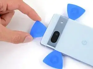
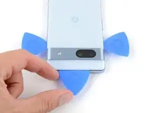
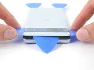
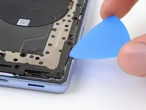
    • Insert a fifth opening pick in the top left corner of the rear cover between 8 mm and 10 mm (0.3–0.4 in) deep, or just over halfway between the tip of the pick and the iFixit logo.

    • If you can't insert the pick, start with the small gap near the camera bar from the previous pick.

    • Slide your pick halfway across the top edge to separate the antenna bracket adhesive. Stop at the halfway point along the top edge.

  17. GgcnyWYLgTYAOWmv
    GgcnyWYLgTYAOWmv
    oGGQmwRQenW5xj6r
    5XaUUxNDxyRnEios
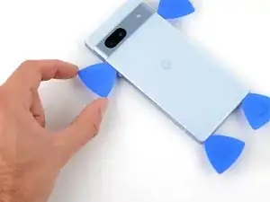
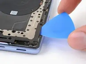
    • Pull your opening pick out to a depth of 3 mm.

    • Slide your pick to the top right corner to slice the rest of the top edge adhesive.

    • Don't insert your pick deeper than 3 mm to avoid damaging the antenna housing graphite tape.

  18. dyVTstLOWl1ngxCQ
    dyVTstLOWl1ngxCQ
    IyKaSb2k3MGZYoS1
    1uRjMyEmQejxDKAQ
    • Remember to angle your picks upward and away from the frame during this step.

    • Roll the top edge pick so its flat edge is under the rear cover.

    • Roll the picks on each side of the camera bar so their flat edges are under the camera bar.

  19. ageyUQfkPqcOVZqj
    ageyUQfkPqcOVZqj
    WIsd2bWoFXn4D4fu
    2viWKASpyWEZQSMB
    • There's a long strip of adhesive securing the rear cover below the camera bar.

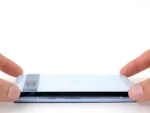
    • Use the opening picks under the camera bar to pry the top edge of the rear cover from the frame.

    • Pry back and forth until the camera bar loosens.

    • Be careful not to bend the rear cover. Only pry enough to loosen the adhesive near the camera bar. If the adhesive feels stubborn, rotate the rear cover side-to-side to further loosen the adhesive.

  20. fUPBYgpMX5swDKEu
    fUPBYgpMX5swDKEu
    xKOSiRhNENJfjiMm
    NBDMbyQjyvfOkxWR
    • Slide the opening picks from the camera bar down the long edges of the rear cover to separate any adhesive that may have resealed.

  21. BOMJgYhYT6AD1SEC
    BOMJgYhYT6AD1SEC
    gWCAw3TeQCw1Ww6Y
    • Remove the rear cover.

    • During reassembly:

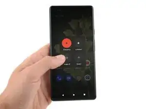
    • Now is a good time to test your phone before sealing it up. Power it on and check that it works. Power it back down before you continue reassembly.

    • Follow this guide to apply new adhesive and install your rear cover.

  22. 5kLOEwNTxZvOYyXh
    5kLOEwNTxZvOYyXh
    jNJRvbGSZH1SHwjy
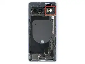
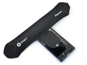
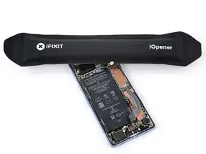
    • Apply a heated iOpener to the flash unit for one minute to soften the adhesive securing it to the logic board cover.

    • Alternatively, you can use a hair dryer or heat gun to warm the flash.

    • Only heat the flash so it's warm to the touch. The battery and surrounding components are susceptible to heat damage.

  23. SXjp1JXKVHFpddrC
    SXjp1JXKVHFpddrC
    xqSIDQS2BJiWrKID
    • Be careful not to slip and tear the flash cable, as it's very fragile.

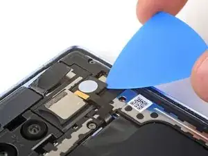
    • Slide your pick under the right edge of the flash to separate the adhesive securing it to the cover.

  24. FxVoF2i4GqWgnrWm
    FxVoF2i4GqWgnrWm
    nVbR1JlDdPZsnvqL
    SCYEfpWuTiK6cLnl
    • If the copper tape lifted away with the flash, use tweezers or your fingers to remove the black foam residue from the logic board cover.

  25. lF5X6B3uFRgPnWFB
    lF5X6B3uFRgPnWFB
    EbYCHAI1NYB4jpdm
    jXTebXfCgAMooay6
    • Be careful not to damage the battery with your tool during this step.

    • Apply a heated iOpener to the underside of the flash for one minute.

    • Hold the neck of the flash cable steady and use tweezers to peel and remove the copper tape from the flash unit.

    • If the copper tape stayed on the logic board cover and you have a replacement, remove the old tape now.

  26. Vw54CX2SKB1UxnJO
    Vw54CX2SKB1UxnJO
    JEXjgWMhlHHKaaNd
    gLIZduHIaJJNjVCO
    • During reassembly:

    • Make sure the small foam spacer is still in the middle of the flash recess in the logic board cover. If not, stick it back to the middle.

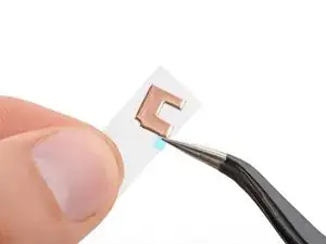
    • Peel the copper tape from the large adhesive liner.

    • Place the copper tape face-down onto the flash, with the cutout toward the neck of the cable.

    • Remove the blue liner to expose the adhesive.

    • Press the flash into place.

  27. jCWwLMYmPwqcdiEx
    jCWwLMYmPwqcdiEx
    S1XQUOTNDcOBlt4D
    • While the Pixel 7a uses Torx Plus screws, standard Torx bits work. Make sure to apply constant, downward force to prevent stripping.

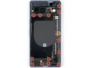
    • Use a T3 Torx driver to remove the thirteen 4.3 mm 3IP Torx Plus screws securing the logic board cover.

    • Use a T2 Torx driver to remove the 1.5 mm 1IP Torx Plus screw securing the right edge of the cover.

  28. ICea21FXMHfa5Brr
    ICea21FXMHfa5Brr
    h2ugsK2hSLiuShQa
    • Insert an opening pick between the bottom right corner of the logic board cover and the frame.

    • Pry up to release the clip securing the cover.

  29. eIY2pHwlfr2jr4YJ
    eIY2pHwlfr2jr4YJ
    ALMXW3AYOBQiZhwt
    RbFAFJ5iGysfcYhF
    • Slowly lift the top edge of the logic board and thread the flash unit through its cutout.

    • During reassembly, thread the flash through its cutout as you lower the logic board into place.

  30. WDd6J1cULDQdHuNp
    WDd6J1cULDQdHuNp
    OekHpOYRC4vJiNtb
    • Remove the wireless charging assembly.

  31. ZhWqgckhmVl1ZeEi
    ZhWqgckhmVl1ZeEi
    SxRBQcy4gIgVTMfm
    1WEPDKcNwZClODqO
    • Use your T2 Torx driver to remove the 1.5 mm 1IP Torx Plus screw securing the connector cover.

    • Use tweezers or your fingers to remove the cover.

    • During reassembly, place the upper left corner of the cover under the hook on the logic board before installing its screw.

  32. 1SDhtN1x3MqmqkPO
    • The Verizon model (G0DZQ) Google Pixel 7a has an extra cable and connector for the 5G mmWave antenna. Unless otherwise mentioned, the rest of the guide procedure is the same for either type of phone.

  33. LJNAJcYOd4aADwEY
    LJNAJcYOd4aADwEY
    rHXL5JjRN3iKAWHJ
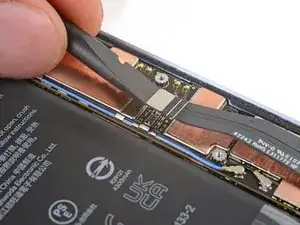
    • Insert the flat end of a spudger under the top edge of the battery press connector.

    • Pry straight up to disconnect the battery press connector.

    • To reconnect a press connector, align it over the socket and gently press down on one side until it clicks into place, then press down on the other side. It might take a few tries to align the connector.

  34. Vsfgbd2CgryBugTr
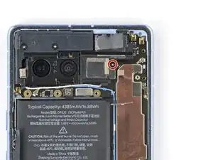
    • Use your T3 Torx driver to remove the 4.3 mm 3IP Torx Plus screw securing the earpiece speaker to the frame.

  35. GJ1CIqmEkHYrMrAk
    GJ1CIqmEkHYrMrAk
    m4gSQLGKOXcOATWV
    K5inHGYjHKHbasAI
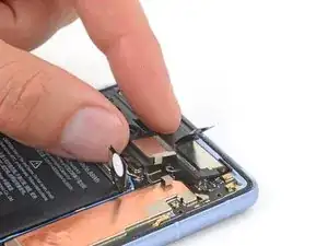
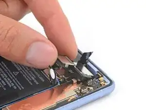
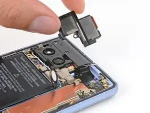
    • Lift the bottom edge of the earpiece speaker upward.

    • Pull the speaker toward the bottom of the phone to free the red gasket from its cutout in the frame.

    • Remove the speaker.

  36. MZJPSRXFNsEtXBA3
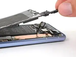
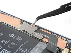
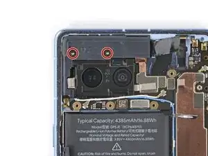
    • Use your T3 Torx driver to remove the two 4.3 mm 3IP Torx Plus screws securing the antenna housing to the frame.

    • During reassembly, hold the housing down while you fasten the screws.

  37. XYRyNm3OjEk1DInd
    XYRyNm3OjEk1DInd
    J46KORGdHvJmKCJC
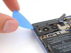
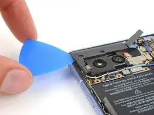
    • Insert an opening pick between the top left corner of the antenna housing and the frame.

    • Pry up to release the clips securing the housing.

    • During reassembly, hold the graphite film out of the way before inserting the housing.

  38. byY4NNECcOxB5WOi
    byY4NNECcOxB5WOi
    ErtmmZ6AlMCBN4yH
    6WXaU2RMpv4gsXlc
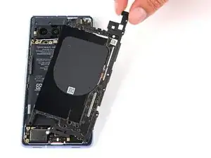
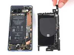
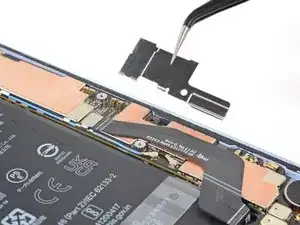
    • Lift the bottom leg of the antenna housing and pull the top edge out from the frame.

    • Remove the housing.

  39. 56tlmbSciskcVSgt
    56tlmbSciskcVSgt
    lxNvKuTBFkPLhdyA
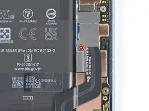
    • Verizon models: Use the point of your spudger to pry up and disconnect the 5G mmWave press connector.

  40. AsPlYvYGi5yqvP4K
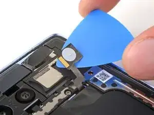
    • Apply a heated iOpener to the front-facing camera for one minute to soften the copper tape adhesive.

    • Alternatively, you can use a hair dryer or heat gun to soften the adhesive. Only heat the tape until it's warm to the touch.

  41. JTAVASjDDEm3JO1e
    JTAVASjDDEm3JO1e
    Znsikf1OYlIUG6Zr
    Ym4rBbwlvPPerKVm
    • Be careful not to touch the rear camera lenses.

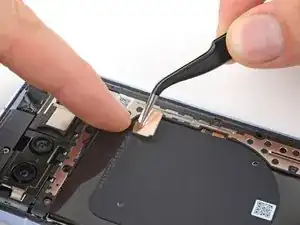
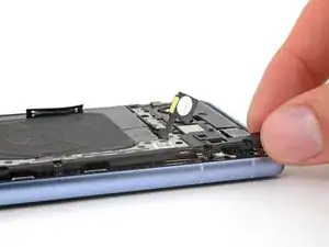
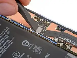
    • Insert the tip of an opening pick under the front-facing camera's copper tape.

    • Slowly peel up the tape from the logic board.

    • If the tape feels stuck, use a sharp tool such as angled tweezers to scrape up the edge of the tape until you can insert a pick underneath.

  42. kcHXwgGeRSkK5Ty6
    kcHXwgGeRSkK5Ty6
    NqmnNGVDMOCTGNUL
    2bBDkCFP3rOsWqLY
    • Be careful not to touch the front-facing camera lens with your tool.

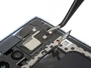
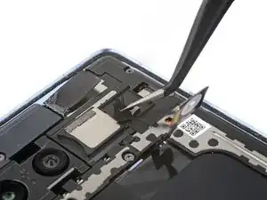
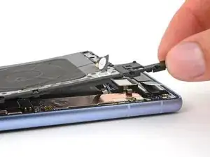
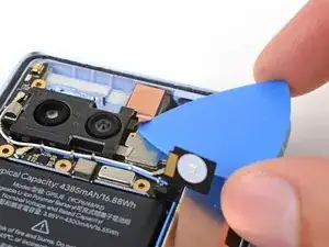
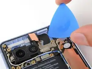
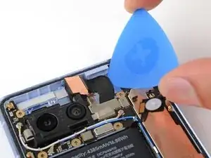
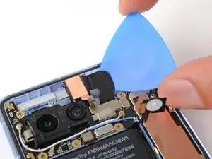
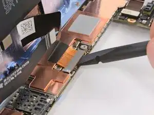
    • Insert the tip of your opening pick between the right edge of the front-facing camera cable and the frame.

    • If the pick can't slide under the cable, lightly heat the cable with a hair dryer or heat gun to soften the adhesive underneath.

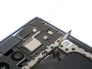
    • Slide your pick underneath the cable to separate the adhesive securing it to the frame.

  43. yhkXpGPkpxTysWhp
    yhkXpGPkpxTysWhp
    SPng6oEewX3o3HVj
    • Be careful not to touch the rear camera lenses.

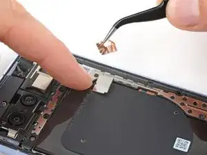
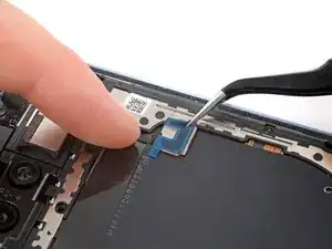
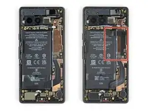
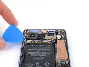
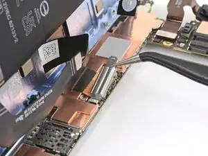
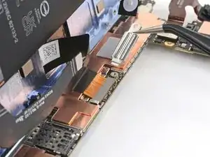
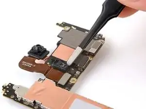
    • Use the point of a spudger or your fingernail to pry up and disconnect the press connector just above the battery.

    • This connector is responsible for the power button, volume buttons, flash unit, and upper microphone.

  44. rLSxDTs25TnxNSST
    rLSxDTs25TnxNSST
    bAhONbUtkDmyMYMF
    E2l4KjZXxvhGEJVs
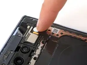
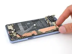
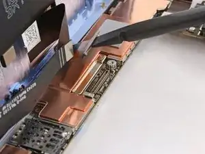
    • Insert your opening pick between the top right edge of the logic board and the frame.

    • Pry up to free the logic board from its recess.

    • Insert your pick in the gap near the white antenna cable and pry up the top left edge of the logic board.

  45. Z4ceANCFHlJRyAOS
    Z4ceANCFHlJRyAOS
    HpyC6jJHpcOXNRqH
    D55KBIGn2fEWE6wP
    • The logic board is delicate. Be careful not to bend it as you free the lower edge from the frame.

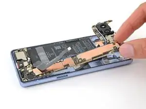
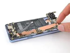
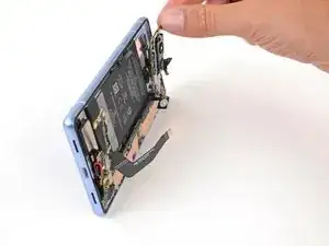
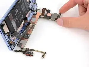
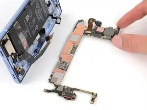
    • Lift the top edge of the logic board from the frame.

    • Pull the top edge of the logic board to the right of the frame so the cutouts of the board lift over the vibration motor and protrusions in the frame.

    • As you pull, guide the charging port out of its recess in the frame.

    • Don't fully remove the logic board yet, as it's still connected to the frame by the screen cable.

    • During reassembly, push the logic board toward the bottom of the frame and press the charging port down until the bottom edge sits flush with its protrusion in the frame.

    • Make sure the flash, front-facing camera, and press connector don't become trapped under the frame.

  46. fATLDFOOuBCCUxUY
    fATLDFOOuBCCUxUY
    XFF3SVsFWcUco5ll
    MU2YrJhvRYDDlOAZ
    • The logic board might fall out of place during this step. Hold it steady, but avoid gripping it by any of the camera lenses or connectors.

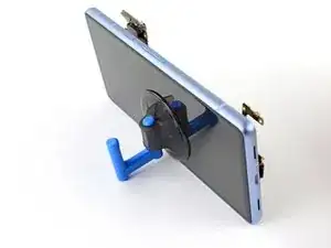
    • Apply your suction handle to the left side of the screen with the handle facing down.

    • Prop up the phone so it stands upright.

    • If you don't have a suction handle, prop up the phone against a sturdy object, such as a heavy box or thick book.

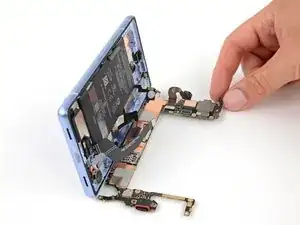
    • Tilt the logic board down and lay it flat. Move any cables out of the way, if necessary.

    • Be careful not to touch the thermal pads on the underside of the logic board.

  47. gy5FUPh2xfAaB5eR
    gy5FUPh2xfAaB5eR
    lQMWTRgtrtwFLFKO
    I65IcdL3huodLgw3
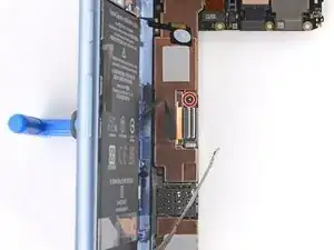
    • Use your T3 Torx driver to remove the 2 mm 3IP Torx Plus screw securing the screen connector cover.

    • Remove the cover.

    • During reassembly, hook the bottom edge of the cover into its slot on the logic board before installing its screw.

  48. L36WEJTtmEQsOVkT
    L36WEJTtmEQsOVkT
    uSxyh1JYZtZ1tXJ5
    • Use the flat end of your spudger to pry up and disconnect the screen press connector.

    • The tension in this cable makes it tricky to reconnect. If necessary, hold the neck of the cable in place with tweezers and align it over the socket before pressing down to secure it.

  49. KRXdsSSDt1n3SH3N
    KRXdsSSDt1n3SH3N
    VPGXhO5exG3K3BYs
    • Remove the logic board from the frame.

  50. 1vNRWQKliTXYAkWv
    1vNRWQKliTXYAkWv
    j4gZSut3VtSEvnmT
    YnWEKRGYHGufFvoB
    • If the front sensor rubber gasket stayed on the frame or became misaligned, remove it and set it aside.

    • During reassembly, place the gasket over the front sensor on the logic board, with the smaller cutout toward the top.

    • Avoid touching the sensor with your fingers or tool.

  51. WQjncNOjqVmwPM4b
    WQjncNOjqVmwPM4b
    UUOsBJHNRHAP1eEO
    • During reassembly:

    • If you're reusing your logic board and the thermal pad is damaged, remove the old thermal pad, clean the surface, and apply a new one.

    • If you have a new logic board and it doesn't come with a thermal pad pre-installed, apply the new thermal pad now.

  52. 3Mi56qKgT3bMcT6g
    3Mi56qKgT3bMcT6g
    ZPPX5MhkCRQJg3Gk
    fNuHLLL11lOpVaZT
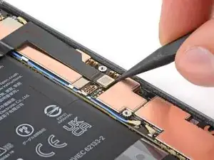
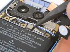
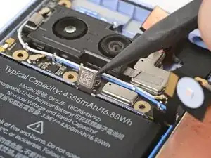
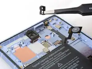
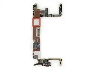
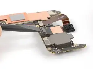
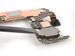
    • Use the flat end of your spudger to pry up and disconnect both rear camera press connectors from the logic board.

  53. QnSQBySLhPhdHWZN
    QnSQBySLhPhdHWZN
    4VEkMx5fZatn5RWt
    • If your work surface is dirty or uneven, put the logic board on a towel or lint-free cloth to protect it.

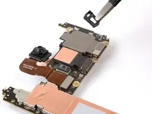
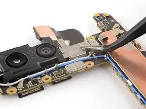
    • Flip the logic board over.

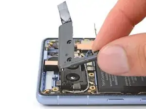
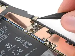
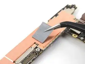
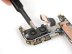
    • Use tweezers to peel the silver conductive fabric connecting the rear camera bracket to the logic board.

  54. 5ilxFfGFUCfKxfBW
    5ilxFfGFUCfKxfBW
    rUhRMcJukQ5PfvAx
    MPEYZmDOqrd3iJ3x
    • Remove the rear camera assembly, being careful not to touch the camera lenses.

    • During reassembly, angle the assembly downward so the press connectors go under the logic board and the tab on the left of the bracket is above the logic board.

  55. 5dGrDk2NwNXnyjYK
    5dGrDk2NwNXnyjYK
    xyWNxGDuMuLlbRFX
    wa5yJYxpfPa1IZGq
    • The wide camera is adhered to the rear camera bracket.

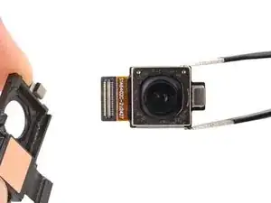
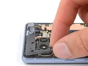
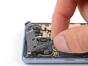
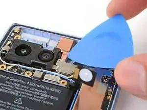
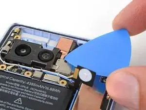
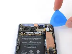
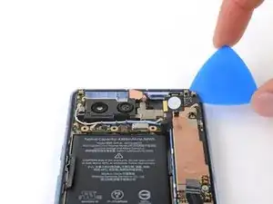
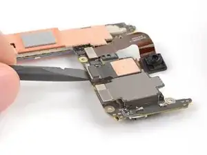
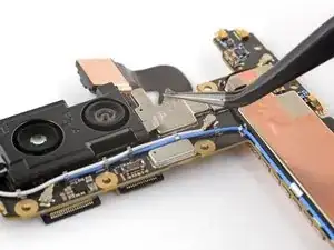
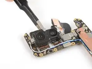
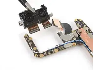
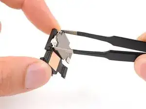
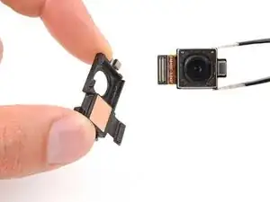
    • Use blunt nose tweezers or your fingers to pry the top edge of the camera from the bracket.

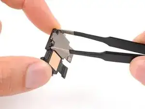
    • Remove the wide camera.

Conclusion

To reassemble your device, follow these instructions in reverse order.

To run a diagnostics test with the built-in Pixel Diagnostic tool, click here.

Take your e-waste to an R2 or e-Stewards certified recycler.

Repair didn’t go as planned? Try some basic troubleshooting, or ask our Answers community for help.

Clay Eickemeyer

Member since: 19/09/22

65190 Reputation

0 comments