Introduction

This repair guide was authored by the iFixit staff and hasn’t been endorsed by Google. Learn more about our repair guides here.

Follow this guide to replace the vibrator motor on a Google Pixel 4a 5G.

The unreinforced display panel on the Pixel 4a 5G is fragile. Pay special attention to the warnings in the opening procedure if you are reusing the screen.

  1. iAN2rDTmwxfXgDHT
    iAN2rDTmwxfXgDHT
    qjIFsMEcokOY4ThY
    5ZFxvfIGjuRlaGZs
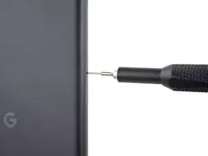
    • Insert a SIM eject tool, bit, or straightened paper clip into the SIM tray hole.

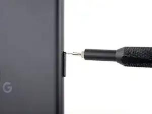
    • Press directly into the hole to eject the SIM card tray.

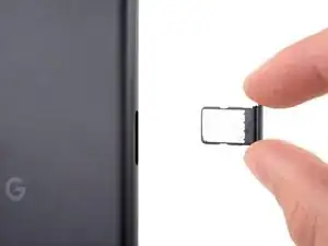
    • Remove the SIM card tray.

  2. BjHu3IQZrLUOOOfX
    BjHu3IQZrLUOOOfX
    whCVBCH5sAn2AjWX
    2jAVOXWTQEtatJHY
    • You will need to pry the screen up to remove it from the phone. Read the following notes carefully before proceeding.

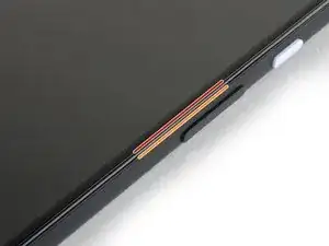
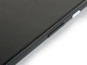
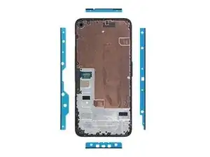
    • Take note of the two seams on the edge of your phone:

    • Screen seam: This seam separates the screen from the rest of the phone. This is where you have to pry.

    • Frame seam: This is where the plastic frame meets the back cover. It is held in place by screws. Do not pry at this seam.

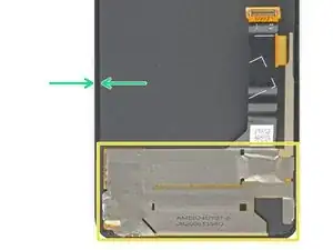
    • Before you begin, note the following areas on the screen:

    • Screen flex cable: Do not insert the opening pick deeper than instructed or you risk damaging this cable.

    • Adhesive perimeter: Prying beyond this narrow perimeter without angling the pick will damage the OLED panel.

  3. 1shUoWThMUmcKsOP
    • Apply a heated iOpener to the right edge of the display for one minute to soften the adhesive.

    • A hair dryer, heat gun, or hot plate may also be used, but be careful not to overheat the phone—the display and internal battery are both susceptible to heat damage.

  4. 22sNsmCMdWrQj2dT
    22sNsmCMdWrQj2dT
    bGfHPsVOSiS6AIx2
    adhLllJ3twF4oWNB
    • If your display is badly cracked, covering it with a layer of clear packing tape may allow the suction cup to adhere. Alternatively, very strong tape may be used instead of the suction cup. If all else fails, you can superglue the suction cup to the broken screen.

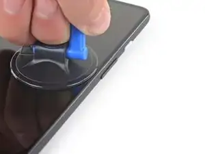
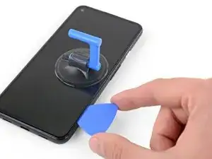
    • Place a suction cup as close to the right edge of the screen as possible.

    • Lift the suction cup with a strong steady force.

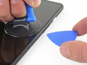
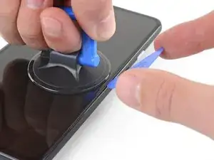
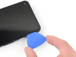
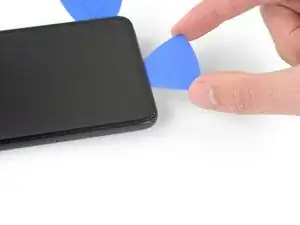
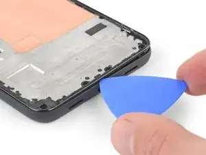
    • Insert the tip of an opening pick into the screen seam no more than 1 mm.

    When "lifting" the suction cup, press down while pivoting the handle away from the front/edge, as if opening a door.

    Soon-Hee -

    For a very cracked screen, I placed clear packing tape on top of the screen to use the suction cup at all. Also had to suction cup and pry/pick at multiple sides of the screen. Small fragments of broken glass won't pry up, so had to use tweezers to pull at glass fragments to release them from the adhesive underneath.

    Soon-Hee -

  5. EKWSEDUtR4UMD4kh
    EKWSEDUtR4UMD4kh
    Fn1sUW1B2NmQPv11
    sNcqGLdHL1lNTpbI
    • This step shows how to insert your pick without damaging the OLED panel. Do this before slicing the adhesive.

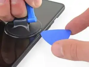
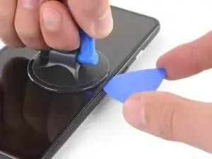
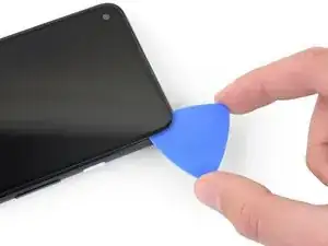
    • With the pick 1 mm into the gap, pivot the pick upwards to a steep angle.

    • At a steep angle, carefully push the pick into the gap about 1/4 inch (6 mm). The pick should slide in below the OLED panel.

    • Stop if you feel the point of the pick hitting a ridge. The pick may be pressing against the edge of the OLED panel. Angle the pick and try again.

    You don't exactly have to be utterly careful about damaging the panel. The glass+OLED screen as a whole is being replaced here. So it doesn't really matter if you accidentally damage the old OLED panel.

    Soon-Hee -

    If only the battery needs to be replaced, be sure to pay attention to the angle at which the pick is moved. Even the slightest deviation and the display is crap. I followed the instructions, but obviously I got to the display somewhere. Unfortunately the display now remains black and I have a flashing green bar at the top. So be careful.

    RiKER “MANiAC -NI-” -

  6. QWiugoSfJ62HsgtF
    QWiugoSfJ62HsgtF
    IDLicOJLOMeF4SGR
    qqjwfukS22qIkiPE
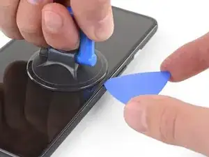
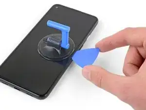
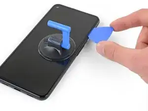
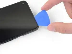
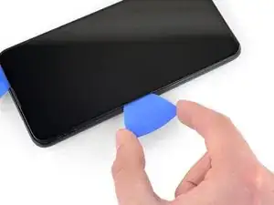
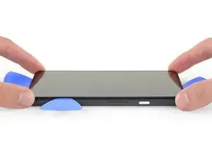
    • Slide the pick along the right edge of the screen to cut the adhesive.

    • Do not insert the pick more than 1/4 inch (6 mm) or you may damage the screen's flex cable.

    • Leave the pick in the bottom-right corner to prevent the adhesive from re-sealing.

  7. kc43OPZSOSOINTxD
    kc43OPZSOSOINTxD
    NQGH5UQSENiB6xJl
    KCRVSKDPmdIuAeAD
    • There's a mesh covering the earpiece speaker on the top edge of the screen. If you don’t have a replacement mesh, take care not to damage or lose this component.

    • The screen adhesive is weak, so you should not need to re-apply heat. If the screen is hard to slice, apply heat to the difficult area for one minute and try again.

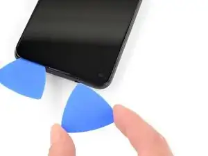
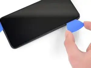
    • Insert another opening pick into the right edge of the phone at an angle where a gap has already formed to prevent damage to the OLED panel.

    • Slide the opening pick around the top of the phone to cut the adhesive.

    • Leave the pick inserted along the top edge to prevent the adhesive from resealing.

    The replacement screen I purchased from iFixit Oceania in Sept 2022 included a new speaker mesh, already attached to the screen.

    Chris -

    The corners seems particularly tricky with the adhesive. Make sure to reapply heat in the corners. I cracked my screen while detaching the corners.

    Patrick Nantel -

  8. yRFEhejVGu2mS5YM
    yRFEhejVGu2mS5YM
    LyPSEqvXePhN1S1X
    l2NREA1KkHMXfF24
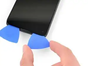
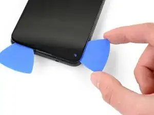
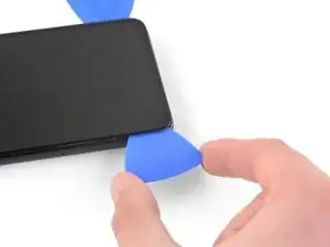
    • Insert another opening pick into the top edge of your phone at an angle where a gap has already formed to prevent damage to the OLED panel.

    • Use the pick to slice around the top-left corner where the camera window is.

    • If the screen is hard to slice, apply heat to the difficult area for one minute and try again.

    • Leave the pick inserted along the left edge of your phone to prevent the adhesive from re-sealing.

  9. pDikbRxBHG5uQeSP
    pDikbRxBHG5uQeSP
    6MwZMZRBrFJivhZO
    T4qM4wocYcLLfWYD
    • Slide the opening pick to cut the adhesive along the left edge of your phone.

    • If the screen is hard to slice, apply heat to the difficult area for one minute and try again.

    • Keep in mind that you are now slicing near the screen flex cable and digitizer.

  10. rBRGU4Pt26RKVkyF
    rBRGU4Pt26RKVkyF
    XxsCXeWkHfbPsNGn
    SeXRscJBBBGL4Bvk
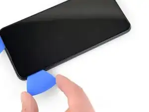
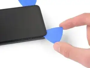
    • Slide the opening pick around the bottom-left corner and across the bottom of the display to cut the rest of the adhesive.

    • If the screen is hard to slice, apply heat to the difficult area for one minute and try again.

    • Keep in mind that you are now slicing near the screen flex cable and digitizer.

  11. 6fD2WJPFoOK4akuO
    6fD2WJPFoOK4akuO
    tcSavu6p6KTwYkYv
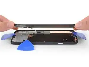
    • Once you have cut around the perimeter of the phone, carefully lift the right edge of the screen, partially opening the phone like a book.

    • Do not remove the screen yet.

    • Use an opening pick to carefully cut through any remaining adhesive.

  12. aOUSRLAvkpRuPCkg
    aOUSRLAvkpRuPCkg
    4mkUQNpF1jiFBN2D
    tROQPeoMEqE2UVTu
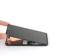
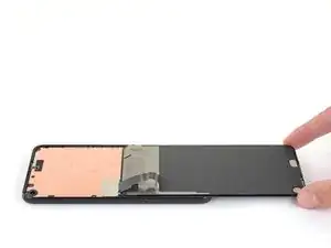
    • Lift from the top edge and swing the screen over the bottom edge until you can rest it glass-side down.

    • Be careful not to put any stress on the attached ribbon cable.

  13. 2LZI2wXoNHhEOebu
    2LZI2wXoNHhEOebu
    NO5L6wkKncYYGiSU
    UwcqyVs6gG1putuL
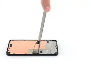
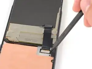
    • Use your fingernail or a pair of tweezers to carefully peel off the tape covering the screen connector.

    • If it is in good condition, you can re-use this tape during reassembly. Otherwise, replace it with a piece of Kapton tape.

    The replacement screen I purchased from iFixit Oceania in Sept 2022 included a new piece of tape.

    Chris -

  14. KyEBG1F6liiXaYU2
    KyEBG1F6liiXaYU2
    MMC1UB5BKiEs4Y6L
    MSOrjLPXIuxOPqmU
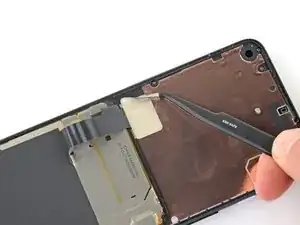
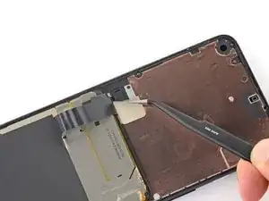
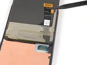
    • Insert the tip of a spudger into the opening of the plastic cover securing the screen flex cable.

    • Pry the plastic cover straight up until it pops out of place.

    • The plastic cover may spring into the air.

    • Remove the plastic cover.
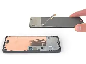
  15. 2DYGeYNekFXLSXaS
    2DYGeYNekFXLSXaS
    wDhTCYcdJViRdGb3
    • Use the tip of a spudger to pry up and disconnect the screen flex cable.

    • To re-attach press connectors like this one, carefully align and press down on one side until it clicks into place, then repeat on the other side. Do not press down on the middle. If the connector is misaligned, the pins can bend, causing permanent damage.

  16. DWFEe15Sga1wOdE1
    DWFEe15Sga1wOdE1
    tvMRDtG5fBofNPYN
    4PGalXujTnMKhxhI
    • Remove the screen.

    • To install a new screen:

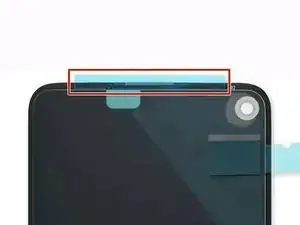
    • Check if your replacement screen has speaker mesh and top edge adhesive pre-installed.

    • If it does, you won't need the top edge adhesive.

    • If it doesn't, remove the larger clear liner from the top edge adhesive and apply it to the screen (not the frame). Make sure the larger cutout lines up with the speaker mesh.

    • Follow this guide to apply the custom-cut adhesive.

    • Use the third photo as a reference to position your adhesives.

    • During the boot-up process after reassembly, the screen will go through a calibration sequence. Don't touch the screen during this process, as it could result in improper touch calibration and create touch issues.

    There are four adhesives provided in the current kit provided by ifixit. They have a blue and clear backing with a thin black strip, as shown on here. The adhesives instructions provided in this general guide are not very clear and I messed up my first one, which made the other three useless leading me to just buy a b-7000 adhesive instead. However, for anyone wanting to correctly use the ifixit adhesives, first line up the black strip on the edge of your phone where the screen will rest and peel off the first clear portion. Then peel off the blue portion and you will be left with a thin black adhesive strip. Do this for all four pieces in the configuration shown on the page linked above and then place your screen on, press down gently, then turn the phone screen down and place some books on to provide stronger contact between the adhesive and the new screen. Good luck!

    Graduate Agriculture -

    thanks a lot!

    Zurdits -

  17. KEvYBcEZpdrsAfBd
    KEvYBcEZpdrsAfBd
    eQ5b4BuHnhCMUOcU
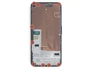
    • Use a T3 Torx driver to remove the nine 4.4 mm-long screws securing the back cover to the midframe.

    • Throughout this repair, keep track of each screw and make sure it goes back exactly where it came from.

    I found 2 extra screws in mine. FYI. (From America)

    L Daniel Wenger -

    I also have 11x T3 in a US model. And the two at the bottom near the USB-C port are shorter by ~1mm than the others.

    Erik Sorensen -

  18. RtefPZcmkFTEXrgU
    RtefPZcmkFTEXrgU
    yUQwE11noW4D1Dld
    CqCRGrmO3UMKLn2D
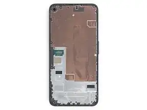
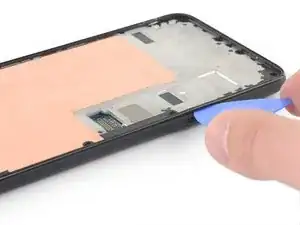
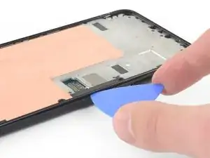
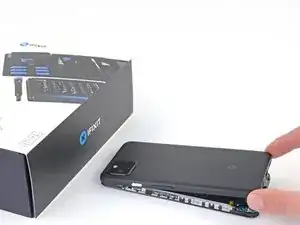
    • Insert an opening pick into the seam between the midframe and the back cover, right above the SIM card slot.

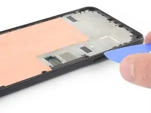
    • Slide the opening pick along the right edge of your phone to release the plastic clips securing the back cover to the midframe.

  19. DwN6JwmOONsMHXbc
    DwN6JwmOONsMHXbc
    IrJi5NJpCuudniIK
    rOQBYd5FMHVEwa5k
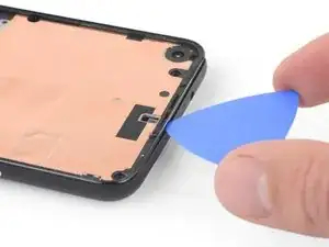
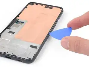
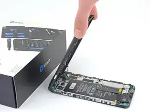
    • Continue sliding the opening pick along the top, left, and bottom edges of your phone until all of the plastic tabs securing the back cover to the midframe are released.

  20. PgVRac5sHOQ3iODq
    PgVRac5sHOQ3iODq
    6PAN5wwTkaTvZyQa
    OhFixdQ4hQAvmupS
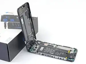
    • Flip your phone over so the back cover is facing up.

    • Carefully swing the back cover up to an upright position.

    • Do not remove the back cover. It is still attached by two ribbon cables.

    • Rest the back cover against an object such as a cardboard box or soda can.

    Be very gentle when removing the back panel, the ribon for the fingerprint broke and I had to wait 4 weeks to obtain it from China

    clem -

  21. jDKwyS2eUQnCHQks
    jDKwyS2eUQnCHQks
    hJ1KQLJNQMMHAH1V
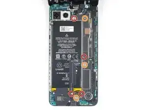
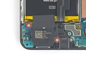
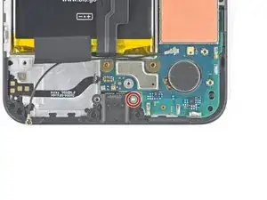
    • Use a T3 Torx screwdriver to remove the seven screws securing the motherboard bracket:

    • Four 4.0 mm-long screws

    • Three 2.1 mm-long screws

    Hi. Thank you for the great Tuto! Do you know where can I find a replacement battery?

    Nicolas AUCONIE -

  22. KSKFj6YZHGMywjN2
    KSKFj6YZHGMywjN2
    UIEdVZsClDs5n5Qh
    • Remove the motherboard bracket.

  23. TFxccfvOP1YxMHcM
    TFxccfvOP1YxMHcM
    cqYqh4wlbqvRsQAY
    • Use the tip of a spudger to disconnect the battery cable from the motherboard.

    Keep in mind this cable when putting board back in place

    Ivan Andrijic -

  24. IQHbbOTClkGHTdIf
    IQHbbOTClkGHTdIf
    RtYLGVYeDDCeOqZY
    • Use the tip of a spudger to pry up and disconnect the fingerprint sensor cable.

  25. 4A6Dtr6TnOOY6YKT
    4A6Dtr6TnOOY6YKT
    amVUEqdrZsnxGop6
    • Use the tip of a spudger to pry up and disconnect the front sensor array cable.

  26. uRJh3UZfSTNVVTkn
    uRJh3UZfSTNVVTkn
    kgPBiWJgrgTtQo55
    • Remove the back cover.

  27. YSDMjLFvkOiBIN2U
    YSDMjLFvkOiBIN2U
    pvPo4nQurdCWFFKV
    • Use your fingers or a pair of tweezers to peel the tape off of the copper foil.

    • The copper foil is thin and easily punctured.

  28. k4oITwh5KBRxkGFu
    k4oITwh5KBRxkGFu
    cDWFY1POSBRqQJCD
    ZHBRsISiX3FpsIfk
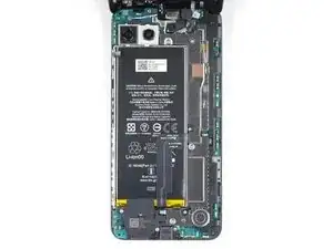
    • Use the flat end of a spudger to disconnect the front-facing camera from the motherboard.

    • Remove the front-facing camera.

  29. gPGvfJ2BNmbdOxaM
    gPGvfJ2BNmbdOxaM
    vsOU2WIJCLTxpDNJ
    • Use a T3 Torx driver to remove the two 4.2 mm-long screws from the loudspeaker assembly.

  30. ntSKhRgZGORxZ6Sy
    ntSKhRgZGORxZ6Sy
    PXA6USdIAJSnTNbN
    nfHoIUfUcwOoU6DY
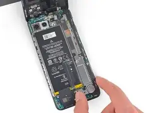
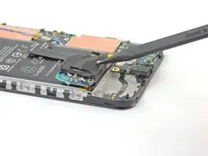
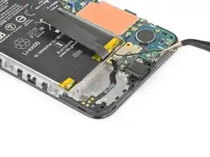
    • Insert the tip of a spudger underneath the loudspeaker assembly.

    • Be careful not to puncture the white membranes on either side of the loudspeaker if you are intending to reuse it.

    • Flip the loudspeaker assembly over so it lightly rests on top of the battery.

  31. JTobpTOjuO1C43rO
    JTobpTOjuO1C43rO
    HMqeKYdpZZsfScqs
    • Use a pair of tweezers to disconnect the antenna cable from the loudspeaker assembly.

    • Grab the metal connector of the antenna cable with your tweezers—not the plastic cable.

  32. 1b1UGOfwZuDWZjhK
    1b1UGOfwZuDWZjhK
    gSkOe1HHGDF6wXu5
    PETUGy3YPCuVRcE3
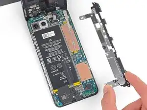
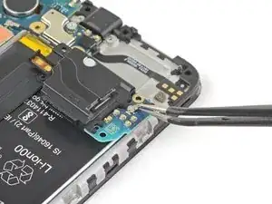
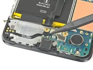
    • Carefully peel the loudspeaker assembly up off the tape underneath it.

    • Be careful not to puncture the white membranes on either side of the loudspeaker if you are intending to reuse it.

    • Remove the loudspeaker assembly.

  33. W2kBfWtewLRoEc1B
    W2kBfWtewLRoEc1B
    VVNtgkmVGIFay6qa
    XTfFRdIaacFWYdhA
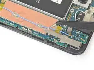
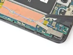
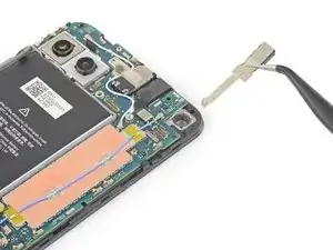
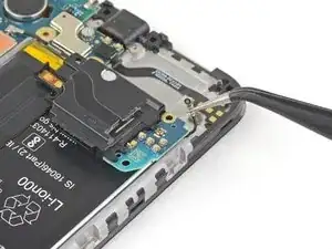
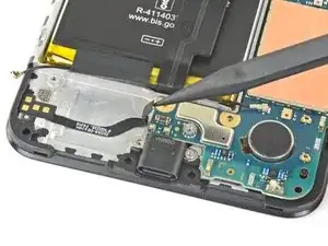
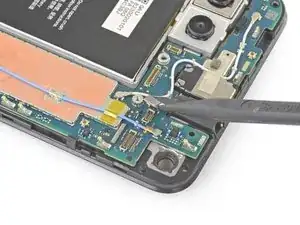
    • Use your fingers or a pair of tweezers to pull the antenna cable out from underneath the tape covering it.

  34. ORNhNAMYn3IAxduB
    ORNhNAMYn3IAxduB
    6EaWgsaZbOPyVG3M
    • Use the tip of a spudger to disconnect the loudspeaker cable from the motherboard.

    Keep in mind this cable when putting board back in place

    Ivan Andrijic -

  35. 2uHYPCZvLjdqylJR
    2uHYPCZvLjdqylJR
    IITrILARWtQjWFxF
    • Use the tip of a spudger to disconnect the headphone jack cable from the motherboard.

  36. qs3sJWeWMdrrtE5E
    qs3sJWeWMdrrtE5E
    cT5LhplRjWju3ZbD
    H3iyKyAPVBrTGj2D
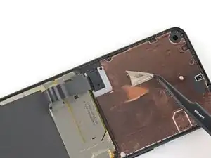
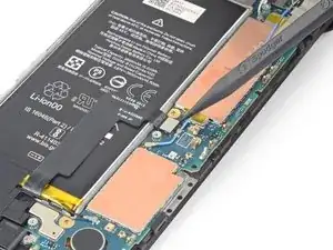
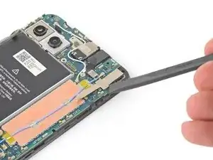
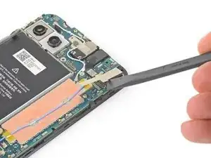
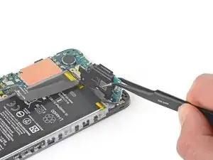
    • Use a pair of tweezers to remove the tape on the earpiece speaker covering the antenna flex cable.

  37. Ds6lPcJcf3ahpRD5
    Ds6lPcJcf3ahpRD5
    6FKr4IYiRmqDWV5F
    • Use a T3 Torx screwdriver to remove the 2.1 mm-long screw securing the charging port.

  38. RilNQ51WmOuTTcra
    RilNQ51WmOuTTcra
    2xKsEv3ZUopf21BS
    • The motherboard is secured to the midframe by plastic clips.

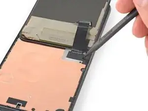
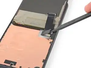
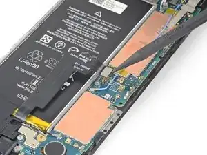
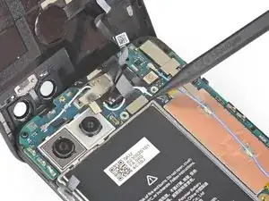
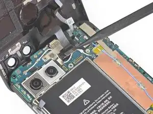
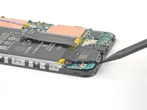
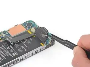
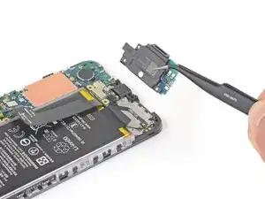
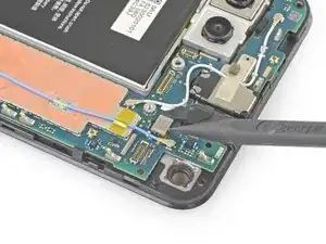
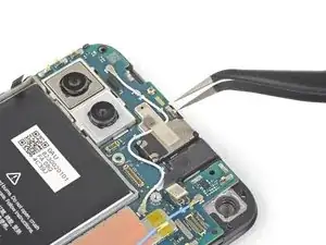
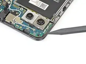
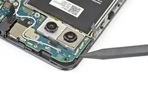
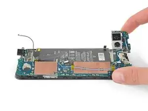
    • Insert the tip of a spudger into the gap between the motherboard and the midframe near the front-facing cameras to pop it free from the first clip.

  39. QEDSCAVESEKxEwZM
    QEDSCAVESEKxEwZM
    mXmkvNSFAXp5PdJT
    lKfZ22JbXNakPQnW
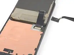
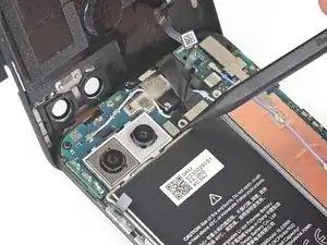
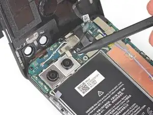
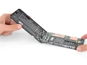
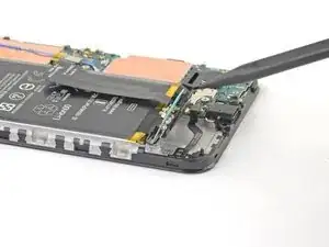
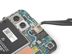
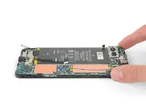
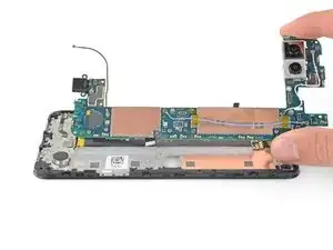
    • Grab the motherboard with your fingers and open it like a book.

    • This will release the rest of the clips.

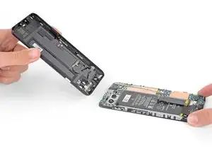
    • Lift the motherboard straight out to remove it.

    Mine (US model) has the two "squeeze sensor" cables on the middle of the motherboard. These need to be disconnected before lifting it out.

    Erik Sorensen -

  40. mm2y3PjD4iaiX2i6
    mm2y3PjD4iaiX2i6
    mgUAOF2o6PJAkns4
    EukiWStlVGKIAZtQ
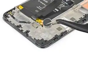
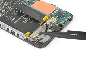
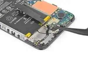
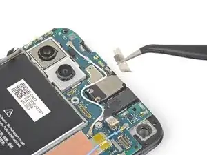
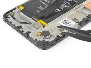
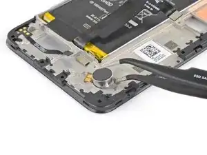
    • Use the tip of a pair of tweezers to pry the vibration motor straight off of the midframe.

    • The vibration motor is secured with some light adhesive.

    • Remove the vibration motor.

    • If the adhesive is too strong, apply a few drops of 90% isopropyl alcohol around the base of the vibrator motor and wait one minute for the adhesive underneath to soften. Then, try again.

Conclusion

To reassemble your device, follow the above steps in reverse order.

Take your e-waste to an R2 or e-Stewards certified recycler.

Repair didn’t go as planned? Try some basic troubleshooting, or ask our Answers community for help.

Sam Omiotek

Member since: 25/02/19

72005 Reputation

0 comments