Introduction

This repair guide was authored by the iFixit staff and hasn’t been endorsed by Google. Learn more about our repair guides here.

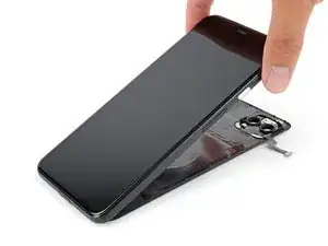
Use this guide to replace the screen on your Google Pixel 4 XL.

Note: Follow this guide to replace a screen that's pre-installed in a new frame (a.k.a. chassis). You'll need to transplant all of your phone's internals to the new screen. If you're replacing the display panel by itself, follow this guide instead.

For your safety, discharge your battery below 25% before disassembling your phone. This reduces the risk of a dangerous thermal event if the battery is accidentally damaged during the repair.

This guide requires a replacement battery. Do not reuse the battery after it has been removed, as doing so is a potential safety hazard.

Caution: Google warns that disassembly of the front laser assembly could result in hazardous exposure to invisible infrared laser emissions. Read their safety warnings here.

  1. vIuPnpQJO4N1YPdv
    vIuPnpQJO4N1YPdv
    RxEtJDHWVlutniFn
    J3GDVmqa5JwKByYK
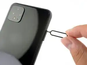
    • Insert a SIM eject tool, bit, or a straightened paper clip into the small hole on the SIM card tray on the left edge of the phone.

    • Press firmly to eject the tray.

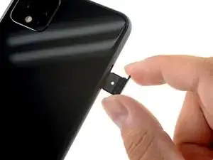
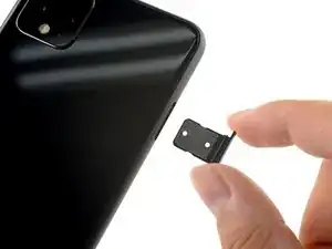
    • Remove the SIM card tray.

  2. Hvp1kuHwJo1AClCp
    • Prepare an iOpener and apply it to the bottom edge of the back panel for one minute.

    • A hair dryer, heat gun, or hot plate may also be used, but be careful not to overheat the phone—the display and internal battery are both susceptible to heat damage.

    I found 2 minutes works best per side. Great Guide btw, thank you for being a strong leader in the fight for right to repair.

    Dennis -

  3. VK4rWKHPMxSBgjeI
    VK4rWKHPMxSBgjeI
    GS4NhjEZM3SCXJcR
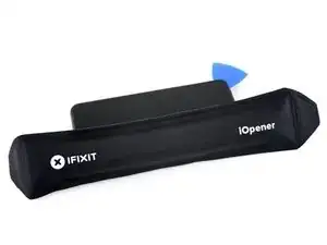
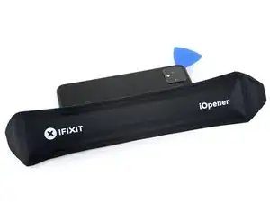
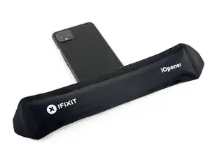
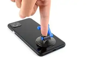
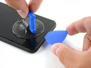
    • Apply a suction cup to the heated edge of the back panel by pressing down on it to create suction, as close to the edge as possible.

    • If your back glass is badly cracked, covering it with a layer of clear packing tape may allow the suction cup to adhere. Alternatively, very strong tape may be used instead of the suction cup. If all else fails, you can superglue the suction cup to the broken panel.

  4. mkgNQMFVCGsIjSWI
    mkgNQMFVCGsIjSWI
    ZcuoIwCBSbZQv1Jp
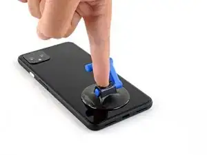
    • Pull up on the suction cup with strong, steady force to create a gap between the back panel and the frame.

    • Depending on the age of your phone, this may be difficult. If you are having trouble, apply more heat to the edge and try again.

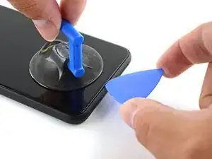
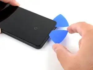
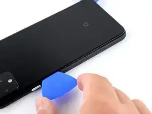
    • Insert the point of an opening pick into the gap.

  5. JPn1p4UL3KeHgTlm
    JPn1p4UL3KeHgTlm
    rerDsh5OJUS5DXft
    pq3vfvBe5v5htEJY
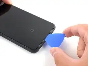
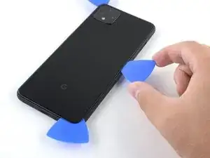
    • Slide the opening pick across the bottom towards the left corner to slice the adhesive.

    • With the pick still inserted, slide it from the bottom left corner over to the bottom right corner to completely slice the bottom side adhesive.

    • Leave the pick inserted in the bottom right corner to prevent the adhesive from re-sealing.

  6. bmjILIENBtpPcpxn
    • Prepare an iOpener and apply it on the left edge of the phone for one minute.

  7. GQ32GFimDFPnCaIN
    GQ32GFimDFPnCaIN
    KwMHik5nQYlWV3HD
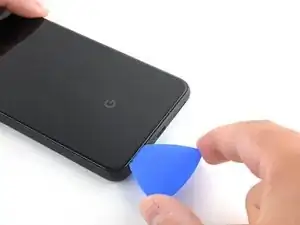
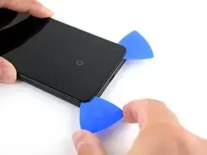
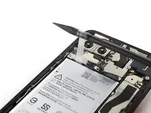
    • Insert a second opening pick underneath the back panel directly over the charge port.

    • Slide the opening pick to the bottom left corner of the phone.

  8. 3wRXCsDVIiReHwDt
    3wRXCsDVIiReHwDt
    TsAtoOUWx5OUtfJw
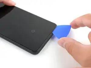
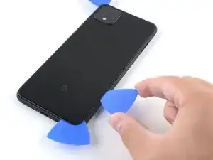
    • Slide the opening pick around the bottom left corner and across the left side of the phone to slice the adhesive.

    • The adhesive can be very gummy. Push the pick in and out in a sawing motion to help with slicing.

    • Stop when you reach the top left corner, near the camera, and leave the pick inserted.

  9. qPt1cI1qIYhrYhrk
    • Prepare an iOpener and apply it on the right edge of the phone for one minute.

  10. 3MaLYKdcXwMGfmHm
    3MaLYKdcXwMGfmHm
    nNHbQECIIHKXCkeA
    dgKAYchvRQfbG4ZJ
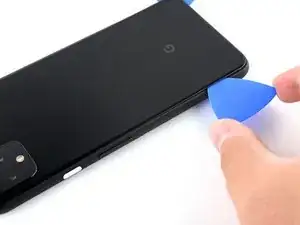
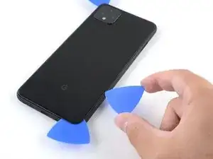
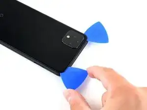
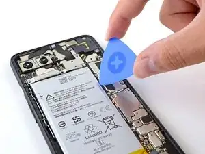
    • With the first two opening picks still in place, insert a third pick on the lower part of the righthand side.

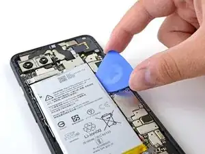
    • Slide the opening pick up towards the top of the phone, slicing the right side's adhesive.

    • Stop when you reach the top right corner, and leave the pick inserted.

    Be careful when slicing the right side's adhesive. The contacts for the wireless charging pad are close to the edge and can easily be bent with the opening pick.

    John G -

  11. pdXuWBOPnOHID4vo
    pdXuWBOPnOHID4vo
    I1Y2GTUYJV4tftII
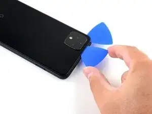
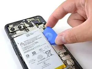
    • Slide the third opening pick around the top right corner and across the top side of the phone, slicing the final strip of adhesive.

  12. OMcDBjHL2YjtAAYG
    OMcDBjHL2YjtAAYG
    R6ddvSVjuedNBCHd
    ILBFbo2bfDKEJJGy
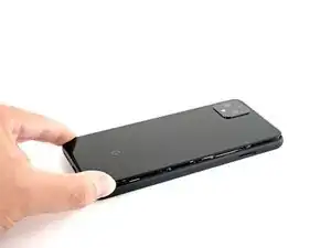
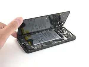
    • Once you have sliced around the perimeter of the phone, carefully lift the right edge of the back cover, opening it like a book.

    • Do not try to pull the panel all the way off yet, as it is still connected to the phone.

  13. NijixQFNhSKKTdcI
    NijixQFNhSKKTdcI
    UxwAwwrw1KYD2pTe
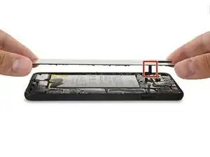
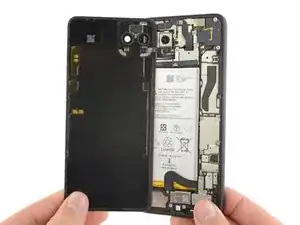
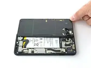
    • Continue swinging open the back panel until you can rest it on the left edge the phone, being careful not to put any stress on the attached ribbon cable.

    • During reassembly, this is a good point to power on your phone and test all functions before sealing it up. Be sure to power your phone back down completely before you continue working.

    “and test all functions before sealing it up.”

    Pretty sure I wont be sealing this up for a few hours, might be worth removing this part of the sentence as it’s confusing…

    Geoff B -

    Geoff B: These are good instructions. Any technician worth his or her salt will test the device for functionality before sealing it up. That’s why it reads, “During reassembly…and test all functions before sealing it up.” Not confusing if you read and comprehend the full pin.

    Jeana Morales -

    No instructions on how to fit new sticky gasket before assembly. Removing old adhesive was a messy business, I used IPA on a cotton bud and removed as much as possible with flat end of spudger and kitchen paper.

    Malcolm Hall -

  14. CbLvKfMPLSOIPeZj
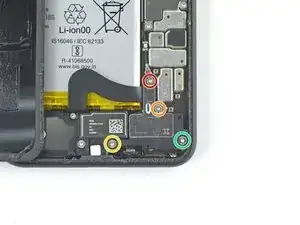
    • Remove the four T3 Torx screws securing the battery connector shield:

    • One 1.8 mm screw

    • One 4.1 mm screw

    • One 4.4 mm shouldered screw

    • One 4.0 mm shouldered screw

    • Throughout this repair, keep track of each screw and make sure it goes back exactly where it came from.

    Anyone know the thread size of the 1.8mm screw mentioned here? Mine went missing, and I need to get a replacement. I've got a bunch of tiny screw kits, but none of them have fit!

    Joseph Sctbunio -

  15. hMmMYeCZjYcTckiS
    hMmMYeCZjYcTckiS
    TbLkCgwKGB3CkFsh
    • Use a pair of tweezers to remove the battery connector shield.

  16. vjiUuPc6ra4hSELD
    vjiUuPc6ra4hSELD
    1FGTf5VCS2ELOc6N
    • Whenever you use the spudger near the battery, be very careful not to puncture the battery.

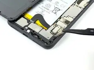
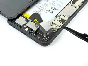
    • Using the pointed end of a spudger, pry the battery connector straight up from the motherboard to disconnect the battery.

    • To re-attach press connectors like this one, carefully align and press down on one side until it clicks into place, then repeat on the other side. Do not press down on the middle. If the connector is misaligned, the pins can bend, causing permanent damage.

    I had the piece from the cable break off inside the connector. How would I go about getting it out

    Dylan DVP -

    What are the 5 copper dots under the battery connector for.

    Brian Davis -

    When you reattach the connector to the motherboard this is a good time to power up and check basic functionality temporarily. Even though it had appeared it was correctly lined, my camera was not functional, in particular the switch button from the rear to the front camera, I was stuck in selfie mode. Then I was getting a message on the screen, possible hardware or software issues. Once I reattached the connecter (several times) until it was correctly inlined, the error went away and I was able to switch from the rear and front cameras.

    bonita pauley -

    That was a good call! Thanks!

    Esther -

  17. jPpHHrKTJhDOLRAB
    jPpHHrKTJhDOLRAB
    35eGEb6Yerdr1akU
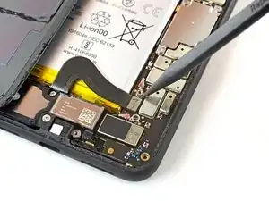
    • Using the flat end of a spudger, gently fold the battery cable over so it doesn't accidentally make contact during the rest of your repairs.

  18. pW6WYwrosLkYWaER
    • Use a T3 Torx driver to remove the two 4.1 mm screws securing the back panel connector cover.

    Wouldn’t it make more sense to use the same (orange) color circles as the other 4.1mm screw?

    Mark Kanzler -

    Maybe Google did it to avoid exchange in the models where they differ

    Daniele Carminati -

  19. XYAjcLAoBQJMddZM
    XYAjcLAoBQJMddZM
    LhAReXLOg44Cb1wP
    • Use a pair of tweezers to remove the back panel connector cover.

  20. laE2TsjjIUOFpHUR
    laE2TsjjIUOFpHUR
    6GAPsQ54pk1QgKgK
    • Using the pointed end of a spudger, pry up and disconnect the back panel connector.

    During reassembly, make sure to firmly connect this back panel connector.

    I had to hold the back panel close to the phone so that the connector stays connected, while putting back all the screws.

    Esther -

  21. CafjDv5LWBPJIgAZ
    • Remove the back panel.

    • During reassembly, follow this guide to install custom-cut adhesives for your device.

    • Follow this guide if you are using a pre-cut adhesive card.

    REASSEMBLY ADHESIVE: This is the step during reassembly that you'll want to set the back glass adhesive strip on (before you reattach ribbons). Set the adhesive strip into the body of the phone with the red tabs down (toward the body of the phone, it will simply rest inside the lip of the phone body). Press the back glass onto the adhesive strip to set the strip onto the back glass, lift the back glass back out of the body of the phone. Next reattach the ribbons, test functions, reattach connector covers, peel red adhesive cover off of the adhesive (on the back glass) then set the back glass into the phone lip. This could have been explained far better but was skipped over and the generic adhesive instructions posted in the comments are useless for this.

    Michael A. Mascaro -

    There are also detailed instructions at answer 742532, "How do I apply new back panel adhesive on a Pixel 4xl?" (sorry it doesn't let me link directly). But it advises adhering the adhesive to the main frame first before the glass. I do notice a slight lip on the main frame on both sides, which seems less forgiving to align with than the glass, so I would imagine doing the frame first would be easier? I haven't done this yet myself, so would be interested in opinions.

    AySz88 -

    Update: it appears the discrepancy is due to a difference between the third-party adhesives and the iFixit "genuine" one. The iFixit one is not mirror symmetric and must be adhered to the glass back first, though it has cutouts that avoid protrusions and facilitate this. The third-party one (I believe) has no such cutouts and thus must go on the frame first.

    However, in trying to follow Michael's instructions, I could not get the adhesive and red tabs off the blue plastic without distorting the adhesive, and had to take the clear side off first. I ended up directly placing the adhesive onto the glass back, without the frame to help align (I posted my method in the above-mentioned answer 742532). The cutouts in the blue plastic seem to have been made with this in mind.

    AySz88 -

  22. RUKtbVcDJKDJ4vyf
    RUKtbVcDJKDJ4vyf
    2RjKl1PhERlca45d
    • Use blunt tweezers to lift up the battery adhesive pull tabs so you can more easily grip them with your fingers.

    • The battery is held in place with three separate stretch adhesive strips, which are connected to a single black pull tab. You can try to pull all three strips out together, but it is easier to cut the black pull tab where it is notched and pull each strip out individually.

    Yellow tab instead of black in my oh so orange Pixel 4XL

    Geoff B -

  23. gyvHQRuRPmvIYwU5
    gyvHQRuRPmvIYwU5
    vNX3QG5sNNajeA51
    • Pull on the black pull tab at a shallow angle with steady force. When the adhesive grows long, roll it around a spudger and continue pulling.

    • Continue firmly pulling up on the adhesive strip with constant force, spinning the spudger every so often to keep the exposed section of the pull tab as short as possible.

    • This may take a lot of force.

    • These adhesive pull tabs are very prone to snapping in half during this process. Try pulling as slowly as possible.

    • If the adhesive pull tabs are not stretching, you can fill a plastic dropper or syringe with high concentration isopropyl alcohol and apply a few drops under the left edge of the battery. Give the alcohol a minute to weaken the battery adhesive.

    • Continue this process for each of the three pull tabs, until all are either out or have snapped in half.

  24. abLR2s31SrdIrv4a
    abLR2s31SrdIrv4a
    EQ3AijgERgpSRHZr
    6QChvAyEewmetqtH
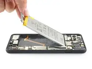
    • If the battery tabs snapped during removal, insert an opening pick on the upper right edge of the battery, slicing the adhesive underneath.

    • Even if you successfully removed all three adhesive pull tabs, using an opening pick to dislodge the battery may be helpful.

    • Don't insert the opening pick on or anywhere below the grip sensor cable, as the pick can damage the charge port flex cable located underneath the battery.

    Strip of glue is only on the top part, only 3 stripes. Becareful passing the gold strip

    Jairon Lopez -

    I wouldn't risk going across the topside of the battery either. the thin cable connecting the side buttons to the board is exposed and is easy to break. Learned from experience.

    Rancid -

    Also broke this grip sensor cable but now what where to get one?

    David Johnson -

    I carefully pulled up the battery from the bottom using the opening pick because my adhesive pull tabs snapped. The battery was so strongly glued to the bottom. I needed to use the other tools in the box to really push the battery out. Could not do it that gently. But anyway succeeded! v

    Esther -

  25. ap4VF3pgdfg1m2OS
    ap4VF3pgdfg1m2OS
    MgqEJbJx3PEN6rIo
    • Don't reuse the battery if it has been deformed or damaged, as doing so is a potential safety hazard. Replace it with a new battery.

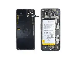
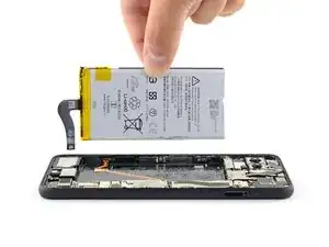
    • Lift the battery up, away from the phone to remove it.

    • To install a replacement battery:

    • Remove any remaining adhesive from the battery well.

    • If you're using stretch release adhesive, apply them onto the battery. Otherwise, apply some double-sided tape, or pre-cut adhesive strips in the phone's battery well, being careful not to cover the charge port flex cable. Peel away any tape liners to expose the adhesive.

    • Temporarily re-connect the battery's connector to the motherboard socket. This ensures that the battery is properly positioned.

    • Lay the battery in place and press firmly.

    • Disconnect the battery connector from its motherboard socket and resume re-assembly.

    The kit comes with a replacement glue strip for the back cover. I would like to have seen some guidance on putting that on. I’m not exactly a beginner at repairing things in general, but this is the first time I’ve worked on a phone. Figuring it out wasn’t too bad, but getting the old glue off enough to make it work added 15-30 minutes to the process.

    Jason Ridenour -

    This is what I’m sitting at now. probably 90% of the original glue off. did you put the replacement strip on the cover first or the body of the phone?

    david janzen -

    For this, I peeled off the white strip and placed the new adhesive (with blue template still on) onto the inside of the back cover, making sure it aligned. I then peeled off the blue sheet and applied pressure and a mostly-cooled iOpener to help it adhere. Worked very well for me.

    Zaeda June -

    You can follow this adhesive guide for installing new battery adhesive!

    Carsten Frauenheim -

    I decided to give up on getting all of the original adhesive stuff. I removed maybe 30% of it and then placed the replacement strip. It seems to be okay, and the back closed all the way.

    Chem -

    FYI the kit includes a new adhesive tapes for the battery. I only found out because I looked inside the kit.

    Esther -

  26. Y2636cxYCqDMOMYU
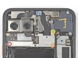
    • Use your T3 Torx screwdriver to remove the following screws securing the rear-facing camera connector cover:

    • One 2.7 mm screw

    • One 4.1 mm screw

    • One 4.2 mm screw

  27. IYTOW6Uw5RUyN6p3
    IYTOW6Uw5RUyN6p3
    RWeWg6wELchjIAy4
    • Use a pair of tweezers to remove the rear-facing camera connector cover.

  28. cN1JSi1L5iR46bHX
    • Use your T3 Torx screwdriver to remove the following screws securing the front-facing camera connector cover:

    • One 4.1 mm screw

    • One 4.0 mm shouldered screw

    • One 4.1 mm shouldered screw

  29. cudpBKH2jgYtt4EG
    cudpBKH2jgYtt4EG
    YYNLQUrmWPyoWS1H
    VSCIPhSCdLIjhNoW
    • Use a pair of tweezers to remove the front-facing camera connector cover.

  30. o2UqLHr23GfLZGMH
    o2UqLHr23GfLZGMH
    RVys6WmSdJFK1WpZ
    tpjEPSHKkXEQMs2F
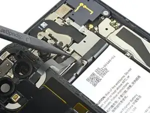
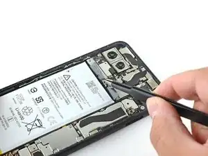
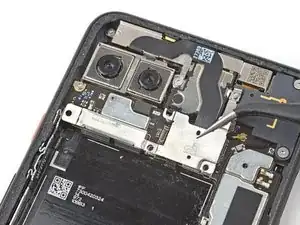
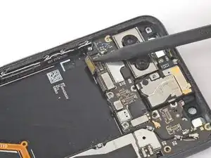
    • Use the pointed end of your spudger to pry the camera and sensor connectors straight up from the motherboard to disconnect them.

  31. LNRctVFQ6IidbPK4
    LNRctVFQ6IidbPK4
    Xx4myXey1WQfWOxJ
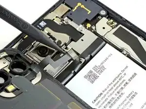
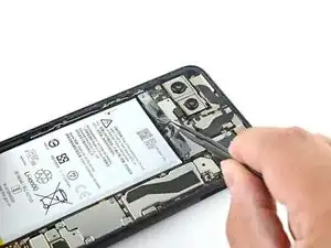
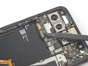
    • Use the pointed end of your spudger to pry up and disconnect the remaining sensor connector from the motherboard.

    • This cable is secured to the phone with some light adhesive.

  32. 2pPRCWiYvyGOg4ZJ
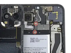
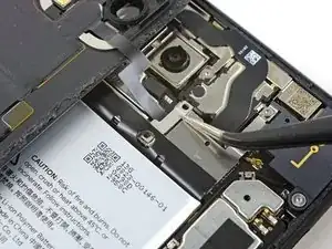
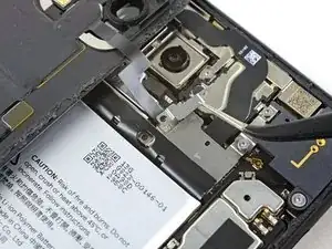
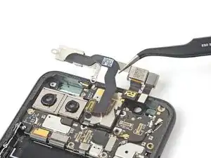
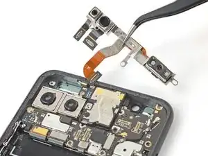
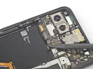
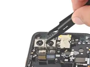
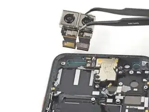
    • Use your T3 Torx screwdriver to remove the following screws from the front camera and sensor assembly:

    • Two 2.7 mm screws

    • One 3.1 mm screw

    I bought the replacement iFixit kit with screen, and in the picture above, the top left screw in the corner wasn't able to be screwed in because there's no hole to screw it in on the replacement screen.

    I continued with just the orange in the middle, and the red by the connectors!

    mahorb -

    EDIT: there are two blue stickers along the inside top of the replacement screen that MUST be removed before putting everything back. This is what I was missing. I'll put a comment at the end if I think it might be worthwhile to add :(

    mahorb -

  33. iZeqvwYSRvnPPDs3
    iZeqvwYSRvnPPDs3
    ygMlhRtDJ3D44JYB
    ksJneTWiYpSRdcf2
    • Use a pair of tweezers to remove the front camera and sensor assembly.

  34. PlMCWcJbp3qpeRt2
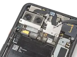
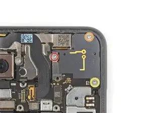
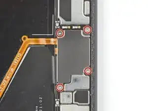
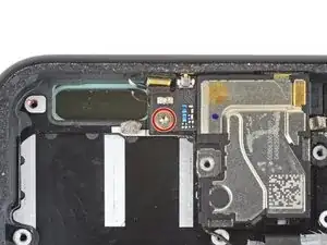
    • Use your T3 Torx driver to remove the four 3.5 mm screws securing the display connector cover.

  35. LxJXCXfMMA53DwEO
    LxJXCXfMMA53DwEO
    SlQAyT2tQYYayPYB
    • Use a pair of tweezers to remove the display connector cover.

  36. bEEIb6eghj1NcjDt
    bEEIb6eghj1NcjDt
    YxM1fKcsfLsDdkYd
    • Use the flat end of a spudger to disconnect the display connector from the motherboard.

  37. tnHeswqgDRq4wHO5
    • Use your T3 Torx driver to remove the 2.7 mm screw securing the motherboard to the frame.

  38. YJATnVwhxlf61NOi
    YJATnVwhxlf61NOi
    cUEIMY5wVYRG5QVa
    xFVEDCiRAmU3qEQc
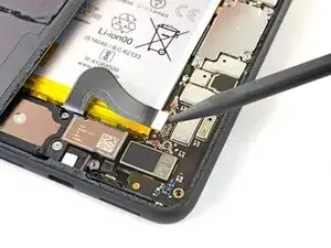
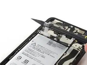
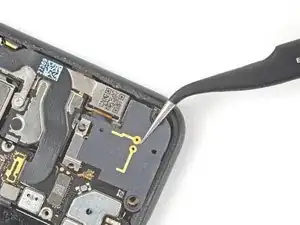
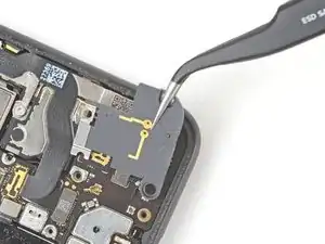
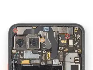
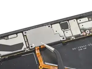
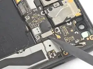
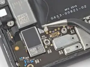
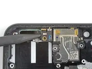
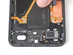
    • Use the pointed end of your spudger to disconnect the three side button and rear-facing camera connectors from the motherboard.

  39. y5ZtjHjDC6wnBTQc
    y5ZtjHjDC6wnBTQc
    ABCokAhEWm4R6skI
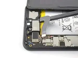
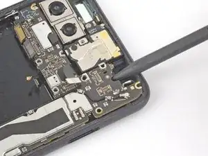
    • Use the pointed end of your spudger to disconnect the earpiece speaker from the motherboard.

  40. Xe6w5iglUgW5XdJp
    Xe6w5iglUgW5XdJp
    CFFkZmcUWjnaLPOU
    mqMg6utntdeFLCm6
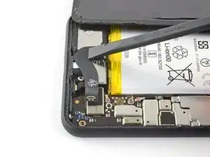
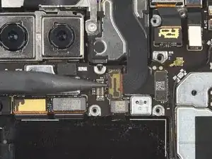
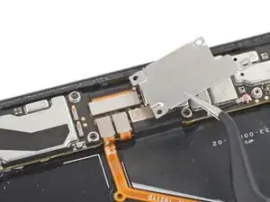
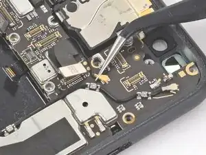
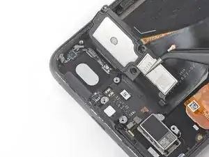
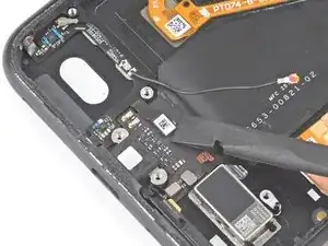
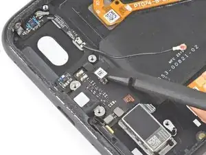
    • Use the pointed end of your spudger to disconnect the two grip sensor connectors from the motherboard.

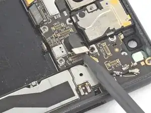
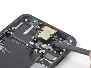
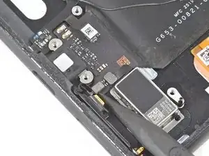
    • Use the flat end of your spudger to disconnect the charge port connector from the motherboard.

  41. cZgsoyG1pAai5RKj
    cZgsoyG1pAai5RKj
    sYH3Hhu42gFE15As
    XTFsUGD5LHWrnVuR
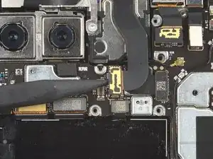
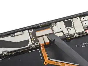
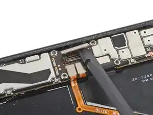
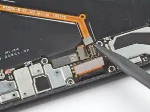
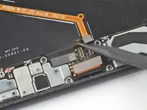
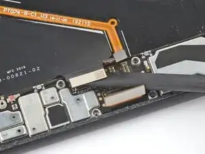
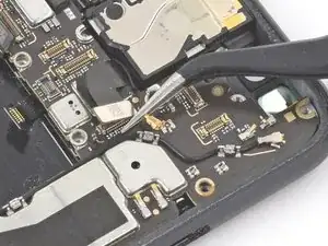
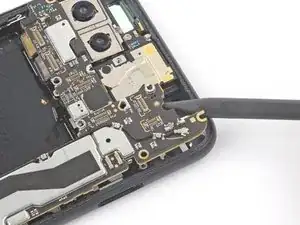
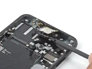
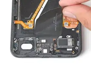
    • Use a pair of tweezers to disconnect the two coaxial antenna connectors from the motherboard.

  42. 2NgieNrhhK51Yhbk
    2NgieNrhhK51Yhbk
    F5hEXEXRFgjjbGFw
    • Use your spudger to pry up and loosen the top edge of the motherboard.

  43. AqmBqMfgISsMRNmV
    AqmBqMfgISsMRNmV
    ZC1hw4MAIdsRQNeh
    2PGjjAkWTTq2QAEX
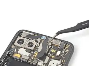
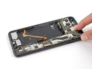
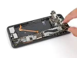
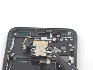
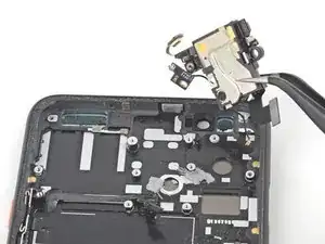
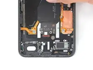
    • Slowly lift out the motherboard, being careful not to snag any ribbon cable connectors.

    • The rear-facing camera module connectors loop around the motherboard, and the camera module is not secured to the phone, so it may lift out with the motherboard during this step.

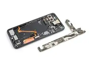
    • Completely remove the motherboard.

    • When reinstalling the motherboard, check that no ribbon cable connectors are caught underneath.

  44. METIMXXStKcbXRfE
    METIMXXStKcbXRfE
    vJdom6ATTuatHXdm
    • Use a pair of tweezers to remove the rear-facing camera module.

  45. yBL5Mg5CsEPUMh5O
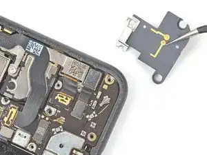
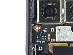
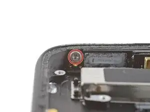
    • Use a T3 Torx driver to remove the 2 mm screw securing the antenna connector board board to the phone.

  46. HbN6gNxOwhN6MYuh
    HbN6gNxOwhN6MYuh
    IrvyBK5YXdQJkvtM
    WaqCDpOZ4myMTcaE
    • Using the pointed end of a spudger, slide the board slightly to the side, away from the top of the phone.

    • Do not attempt to entirely remove this board; it's still connected to the earpiece speaker.

  47. tKcMedqnFWO2yAMw
    tKcMedqnFWO2yAMw
    A2TaGYYfahQAYAMP
    AHPO4ElPKRZQGjDm
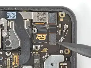
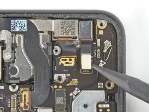
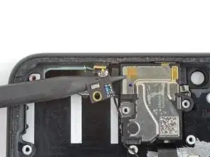
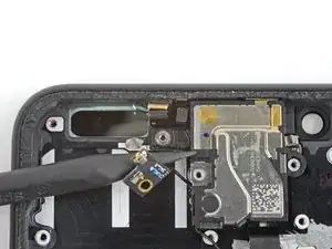
    • Use the pointed end of your spudger to peel the microphone away from the light adhesive securing it to the phone.

    • Ensure the microphone is completely detached from the top frame before continuing to the next step.

  48. OStYrVloqNjZEvVc
    OStYrVloqNjZEvVc
    kBgvRh2NVRGxfVmM
    • Use the flat end of your spudger to pry the earpiece module away from the phone's midframe.

    • The earpiece module is attached with some light adhesive, and should come up without too much force.

  49. hxeVaDBcZ6MkhRcJ
    hxeVaDBcZ6MkhRcJ
    RqC2YDaLxhGAJDm6
    DHR2ILLLamWEhkIu
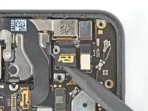
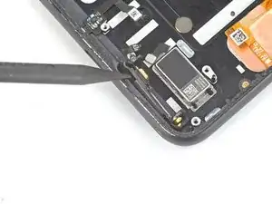
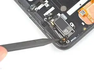
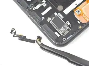
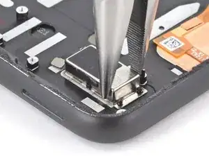
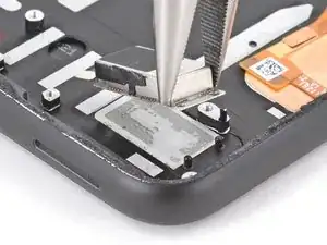
    • Use a pair of tweezers or your fingers to pull the earpiece module away from the light adhesive holding it to the phone's top frame.

    • Remove the earpiece module.

  50. TLIN3AApkWypcegJ
    TLIN3AApkWypcegJ
    eWbB5E3fiKSwJ6s2
    • Use a pair of tweezers to remove the earpiece speaker and Soli motion sensor assembly.

  51. AF1AceZPSRJQlfoV
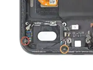
    • Use your T3 Torx screwdriver to remove the three screws securing the loudspeaker:

    • One 4.1 mm screw

    • One 2.7 mm screw

    • One 4.4 mm shouldered screw

  52. VkgQlqRdEbQ2O6au
    VkgQlqRdEbQ2O6au
    ps4YMmBKxtBWGZfp
    AggNjKeoZ2NdHUdZ
    • Use a pair of tweezers to lift the loudspeaker up and away from the frame.

    • Remove the loudspeaker.

  53. 12gnGYGGVKYQwe2B
    12gnGYGGVKYQwe2B
    m4KLOspHFGZjEcQX
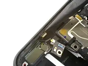
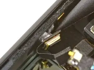
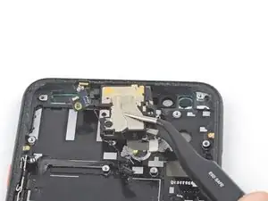
    • Use the pointed end of your spudger to disconnect the two antenna press connectors from the charging assembly.

  54. oNXS1uVqnRko5Eb2
    oNXS1uVqnRko5Eb2
    t1w1AfWZVMEh6qcu
    gEw4FCqC6YBs5Wlr
    • Disconnect the antenna press connectors from the charging assembly.

  55. HNb2G3CenUFjHBks
    HNb2G3CenUFjHBks
    PDwcQ4eun2VcIFCu
    YEL5Wi4uldkAiBg4
    • Peel back the ribbon cable until it is fully separated from the frame.

    • The ribbon cable is secured to the frame with some light adhesive.

    • Remove the charging assembly.

  56. KHPHsZRhF4AKM2Kw
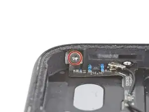
    • Use a T3 Torx driver to remove the 3 mm screw securing the bottom microphone assembly to the bottom right corner of the frame.

    &&^&^$^ impossible.

    Zakariya Yusuf -

  57. TKWkeIxsr4nDruM1
    TKWkeIxsr4nDruM1
    6Hg2GIwRE6FmeTKx
    nKZnmuncX6UmcK1F
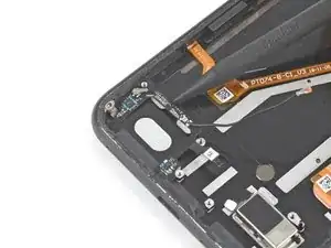
    • Insert the pointed end of a spudger into the divot between the microphone assembly and the frame.

    • Slide the pointed end of the spudger from left to right, separating the microphone assembly and the frame.

    • Remove the microphone assembly using your fingers or a pair of tweezers.

  58. l2OxQfWS1QIcwih4
    l2OxQfWS1QIcwih4
    3MNQM5UruB5dBAT2
    XSCRtjgTxCUUtIdr
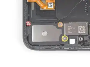
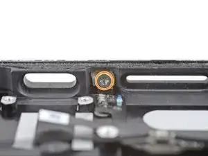
    • Use a T3 Torx driver to remove the two screws securing the antenna to the frame:

    • One 2 mm screw on the left side of the frame

    • One 2 mm screw on the bottom side of the frame

  59. IJl4KJXqd25XpkLE
    IJl4KJXqd25XpkLE
    Fmebr52xNmAMYf5e
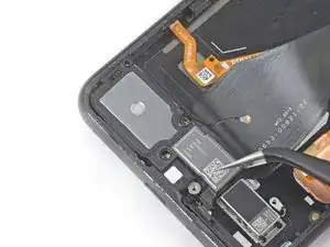
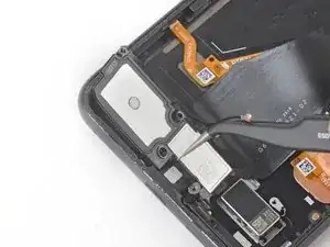
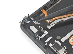
    • Insert the pointed end of a spudger underneath the antenna's ribbon cable and gently pry up to peel the cable from the frame.

    • The antenna's ribbon cable is secured to the frame with some light adhesive.

    • Remove the antenna.

  60. Awup1YpLR1ixkyvA
    Awup1YpLR1ixkyvA
    AMJHJF3ZXE6nQTUG
    • Use a pair of pliers to firmly grip the vibration motor near the bottom right of the device.

    • Pull straight up with steady force until the motor separates from the frame.

    • Grip the vibration motor by the side opposite its cable and be sure not to damage the cables covering the rest of the motor.

  61. dOAeFtwE2uTcLq4d
    • You're now left with the screen.

    If you get a replacement screen and about to start in reverse order, take off the two blue protection films along the top of the replacement screen.

    I noticed too late and had to disassemble a bit, take them off, then reassemble again! Best of luck!

    mahorb -

Conclusion

Compare your new replacement part to the original part—you may need to transfer remaining components or remove adhesive backings from the new part before installing.

To reassemble your device, follow the above steps in reverse order.

Take your e-waste to an R2 or e-Stewards certified recycler.

Repair didn’t go as planned? Try some basic troubleshooting, or ask our Answers community for help.

Clay Kim

Member since: 16/02/21

9619 Reputation

0 comments