Introduction

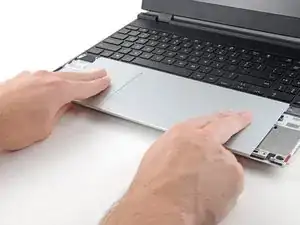
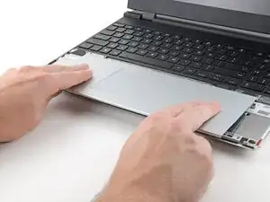
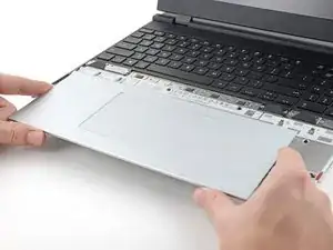
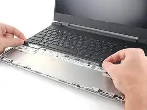
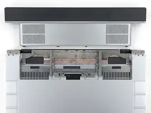
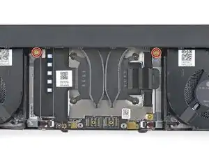
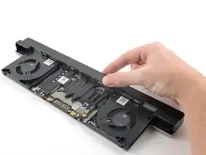
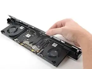
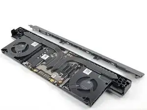
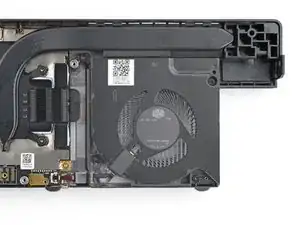
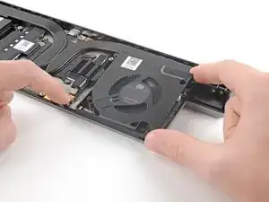
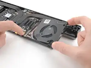
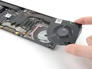
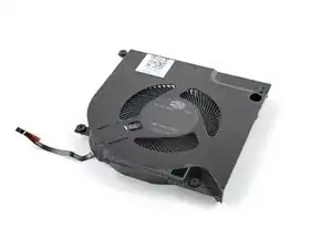
Use this guide to replace one or both of the graphics module fans in your Framework 16" laptop.

Note: the laptop used in this guide is a generic setup of one US keyboard, one numpad module, and two touchpad spacers. Your setup might vary, but the procedure should remain the same.

  1. FyZqYQXlGGSUVdfO
    FyZqYQXlGGSUVdfO
    ddbQkHnXk5QEvLfj
    • Unplug all cables and fully shut down your laptop.

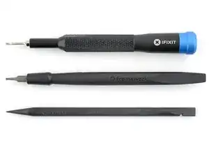
    • If your repair requires a spudger, a T5 Torx, or a Phillips screwdriver, you can use the included Framework screwdriver. Whichever works best for you!

  2. Ij5tZGZrkdXZTD2w
    Ij5tZGZrkdXZTD2w
    LCNSyJH2IOKHeHb2
    4pRwkxTQGNlUhlIx
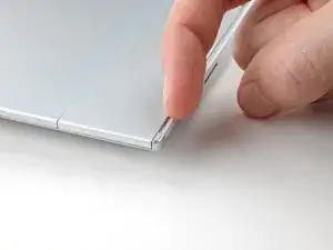
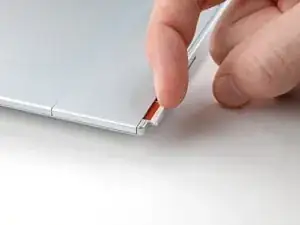
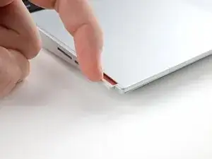
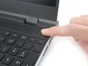
    • Use your fingernail to pull out the two Input Module latches and unlock them.

    • The latch will show red if it's unlocked.

  3. oRA2BGYySG6cv4UI
    oRA2BGYySG6cv4UI
    EjHQwVWhreadODGC
    Qd4HyChkTncRj6NB
    • Use your fingers to slide the touchpad spacer toward the bottom edge of the laptop and unclip it.

    • If you're having trouble, check if the corresponding Input Module latch is properly unlocked.

    • Lift the touchpad spacer off the laptop and remove it.

  4. PIQuXTPBOmiCmpTP
    • Repeat the same procedure for the other touchpad spacer.

  5. XUyEDC4iKWYV5Tnt
    XUyEDC4iKWYV5Tnt
    pTmsgnLnOsotLW2D
    IAOYbMHag2mlLGT6
    • Use your fingers to slide the touchpad toward the bottom edge of the laptop and disconnect it.

    • If you're having trouble, check if the Input Module latches are properly unlocked.

    • Lift the touchpad and remove it.

    • During reassembly, perform the following:

    • Place the touchpad flat on its cutout so its clips are properly aligned.

    • Press the touchpad down and slide it into place so it lines up evenly with the bottom edge of the laptop.

  6. EMiltNMDCZ2ZfrqP
    EMiltNMDCZ2ZfrqP
    kI1lOpjnUTZDpfZt
    5UtiQGpQXVRbA4QM
    • The keyboard is held in place with strong magnets. Apply gradually increasing force to avoid having the keyboard violently eject.

    • Grip the two pull tabs along the bottom of the keyboard.

    • Lift the pull tabs until the keyboard magnets release.

    • Remove the keyboard.

    • During reassembly, make sure the keyboard is seated properly on its alignment pegs and sits evenly with the edges of the laptop.

  7. F6EtPOhQyBDv3K5Q
    F6EtPOhQyBDv3K5Q
    fJDM6TD5UaZ5BvkI
    xeLqBn636iKVEMk2
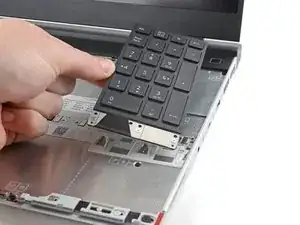
    • The numpad is held in place with strong magnets. Apply gradually increasing force to avoid having the numpad violently eject.

    • Grip the pull tab at the bottom of the numpad.

    • Lift the pull tab until the numpad magnets release.

    • Remove the numpad.

    • During reassembly, make sure the numpad is seated properly on its alignment pegs and sits flush with the edges of the laptop.

  8. P3glQ1GTsPkGyH2M
    P3glQ1GTsPkGyH2M
    d32mDZehfiKIfDdr
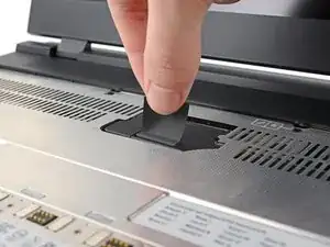
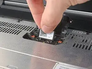
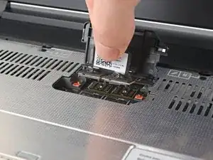
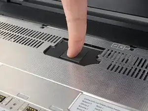
    • Lift the interposer door by its black pull tab and let it rest upright.

  9. Dx6pYosnUoQxCI4K
    Dx6pYosnUoQxCI4K
    WjcFdJtjZXC3xaC3
    OvJuQeMB5CSFuiOj
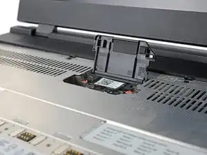
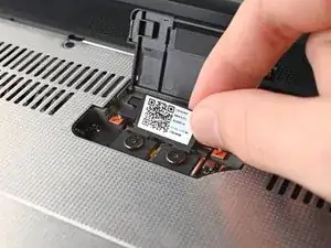
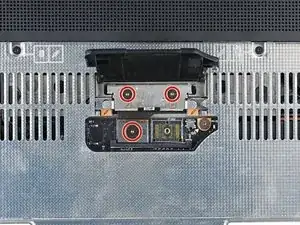
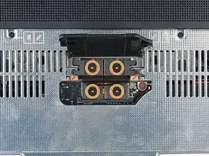
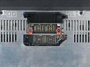
    • If you have the graphics module installed, your interposer will have four screws. Otherwise, you'll have three screws.

    • Lift the pull tab on the interposer and let it rest vertically to access all of its screws.

    • Use a T5 Torx screwdriver to loosen the three captive screws securing the interposer.

    • If you have the graphics module, use a T5 Torx screwdriver to loosen the four captive screws securing the interposer.

  10. JCGNrUTZIArDZrTg
    JCGNrUTZIArDZrTg
    5FI2UdiBZKWLdjTN
    • Lift the interposer by its pull tab and remove it.

  11. 1xM31Q5HLnOx22yi
    1xM31Q5HLnOx22yi
    UHHMbdlMQWnQi53g
    • Use a T5 Torx screwdriver to loosen the two captive screws securing the expansion bay.

    • Close the interposer door before continuing.

  12. TeVHBGFGElOJYSOm
    TeVHBGFGElOJYSOm
    NHGx6nxX1fGYZqFg
    aMrIWYXXbVGksg63
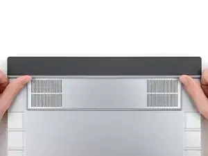
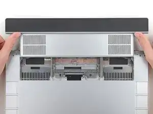
    • Close your laptop and flip it over.

    • Slide the expansion bay out of the laptop and remove it.

    • The bay should slide out easily. If you feel any resistance, check that the screws holding it in place are fully loosened.

  13. ycineNF4I4VAyjHU
    ycineNF4I4VAyjHU
    RNHAoUPeMJ3EdNRD
    yKWjhf1LHNCYAoVe
    • Flip over the graphics module so the fans are facing you.

    • Use a T5 Torx screwdriver to remove the four 3.6 mm‑long screws securing the graphics module cover:

    • Two screws on the flat surface of the module, next to the fans.

    • Two screws on the thin edge of the module, near the ends. You'll need to flip the module on its back edge to access them.

  14. HV5KZaEvDLNgvBr5
    HV5KZaEvDLNgvBr5
    RZfIBV3Uyw3OAlWu
    WleJcSPlgSHrBxZQ
    • Use your fingers to lift the graphics module cover off the expansion bay and remove it.

  15. WwDxIsU5DMwQTZPH
    WwDxIsU5DMwQTZPH
    dYDlCSofC2doJkYO
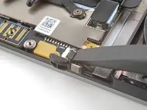
    • Use the flat end of a spudger, or a clean fingernail, to lift up and release the locking tab on the fan ZIF connector.

  16. DbJwmBOQCEEaBmoV
    DbJwmBOQCEEaBmoV
    FIWyWdKFyDTpDAA1
    • Use tweezers, or your fingers, to grip the brown pull tab and slide the fan cable straight out of its socket.

  17. X3QUsEDQUxw6MCJq
    X3QUsEDQUxw6MCJq
    JnQnHrsIFiL2HDtR
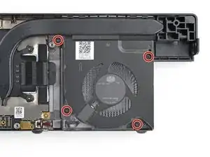
    • Use a T5 Torx screwdriver to loosen the four captive screws securing the fan.

  18. LYEjJqJw1SAaYvBK
    LYEjJqJw1SAaYvBK
    XTiLbIRQCq1lo4xM
    iK3GnmfKJqUJAE35
    • Use one hand to press the fan cable flat to the module.

    • Use your other hand to pull the fan out of its housing, making sure to thread the cable though its slot.

    • Remove the fan.

Conclusion

To reassemble your device, follow these instructions in reverse order.

Take your e-waste to an R2 or e-Stewards certified recycler.

Repair didn’t go as planned? Try some basic troubleshooting, or ask our Answers Community for help.
Alex Diaz-Kokaisl

Member since: 16/01/22

117889 Reputation

0 comments