Introduction

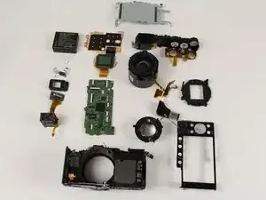
Do you have broken parts inside your camera that you don't see guides for? Do you want to see what makes your camera work? Do you need to recycle your camera and want to do it properly? This guide will show you how to completely disassemble your Panasonic LUMIX DMC-LX100.

  1. BxPhxv5RcJCniZEC
    BxPhxv5RcJCniZEC
    24qG21PMoPF15qTP
    bFoIAGf2cKngBUWn
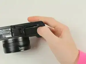
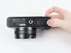
    • Looking at the bottom of the camera, slide the OPEN/LOCK switch to the left into the OPEN position.

    • The battery housing door should swing open.

  2. cBlsvJMuCeuhuPtd
    cBlsvJMuCeuhuPtd
    UbCCpay2LH1tquto
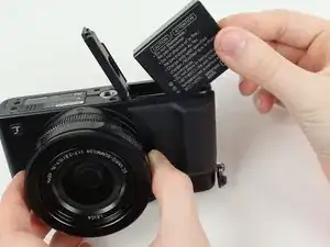
    • Flip the inside switch up to release the battery.

  3. nIDnaFMiZ3kI64Po
    • Grip the edge of the battery and pull it out.

    • Use a LUMIX Panasonic DMW-BLE9PP Battery Pack for replacement.

    How to take off the battery housing door? Is it necessary to take the front cover off in order to do it?

    Boser Hund -

    Hello, how to take the battery housing door off on lx100? Is taking the front cover off necessary? The whole tutorial is great but the most common part that breaks often is not covered.

    Boser Hund -

  4. i5GO6TVIDIAZVyq5
    i5GO6TVIDIAZVyq5
    eAhZCZDBGBUWH21H
    FHeIwipHxv5L3VCm
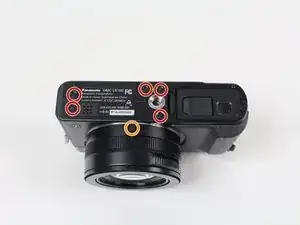
    • Some of these screws may have adhesive to keep the camera from being taken apart so push hard with the screwdriver and turn slowly to avoid stripping screws.

    • Use a Phillips #000 screwdriver to remove the five 4.5 mm screws located on the bottom of the camera and the top one on the left side, with the lens facing you.

    • Use a Phillips #000 screwdriver to remove the two 3.5 mm screws, one below the lens and one on the left side.

    • Use a Phillips #000 screwdriver to remove the 7.1 mm screw from the right side of the camera.

    Only the screw below the lens was 3.5 mm. Both screws on the left side were 4.5 mm

    pinkerton.farm -

    The screw on the lens and the screw nearest to it (beneath the tripod mount) do not need to be removed if you only want to remove the sensor to clean it.

    Stefan -

  5. OKgUjfuOIAh3guxS
    • The viewfinder in this picture is taken off of the camera to more easily see where the screw is located. It is not actually removed from the camera.

    • Use a Phillips #000 screwdriver to remove the 2.5 mm screw underneath the viewfinder.

    • Pull the black plastic piece off of the viewfinder.

    This was a 4.5 mm screw.

    pinkerton.farm -

    To pull it off, pull the bottom side first. Removing this cover offers the advantage to clean the viewfinder glass.

    Stefan -

    This screw has a coarser thread pitch than the others

    Ren Yuthok -

  6. gPRtPhAdM2ILbnQl
    gPRtPhAdM2ILbnQl
    FtP4fLv5KibXFEEJ
    vmJ6FTnvWQR1I1bo
    • Slide out the black plastic piece that acts as a placeholder for an attachable lens on the top of the camera.

    • Remove the small metal insert that rests beneath the black plastic piece by pulling outward, away from the lens side of the camera.

    • You may need a spudger or prying device to remove the metal piece by lifting the back end up.

  7. YURTry4UmQDGFqMR
    • Some of these screws may have adhesive to keep the camera from being taken apart so push hard with the screwdriver and turn slowly to avoid stripping screws.

    • Use a Phillips #000 screwdriver to remove all four of the 7.1mm screws that are under the metal piece.

  8. hKoYyqAMN5tpVIPF
    • There may be adhesive holding the back on, so pry carefully to not break any of the ribbon cables underneath.

    • Pry off the back of the camera using a spudger starting from the top right side of the LCD screen.

    The top right is stuck that i cannot pry off the back plate, is there a screw or some adhesive ?

    parentshyps -

    there's a screw that mount the 4-way scroll wheel to the back plate, DO NOT try to pry off the back plate as shown in the photo by force.

    You should pry off the back plate with the scroll wheel, and then detach the flat cable on the camera.

    jenghanhsieh -

    My device had a additional screw underneath the rubber piece. I had to remove the rubber piece partially and then I could remove the screw (silver one with a big, flat head). Now I could continue to remove the back. Also the 4-way scroll wheel and buttons are screwed to the back plate, so two screws this guide doesnt show.

    Rincewind -

    Agree with the comments above. The screw pictured in Step 9 is behind the rubber thumb rest in step 8 and must be removed before the back can be taken off. Also, the buttons are attached to the back plate by a screw, so will come off with the back plate. They are attached to the motherboard with a ribbon cable that must be disconnected.

    Damon Schreiber -

    I think this is the difference between the LX100 and the LX100S versions. I had the same challenges above.

    Trigg Bowlin -

    I also had a screw under the rubber thumb pad. And the rubber thumb pad should not be completely removed as it was attached to the back plate via a small screw from the inside of the back of the camera.

    Looking at the back of the camera, only remove the left (thinner) side of the rubber thumb pad in order to get access to the hidden screw. This screw needs to be completely removed before prying the back off the camera.

    pinkerton.farm -

    Im struggling to get it off where the Fn3 and Fn2 buttons are, any suggestions?

    ellie1 -

    for the ZIF cable connectors, DO NOT LIFT ON THE WHITE PART. The ZIF connectors here have a black bar on the back that you left up on.

    Ren Yuthok -

    again , screw behind thumbrest needs to be removed , certainly on the LX100 mk 1 variant , otherwise a really helpful article !

    swlewthwaite -

  9. CpPQLhhfo3EQVQO2
    • Use a Phillips #000 screwdriver to remove the 7.5mm screw on the top right of the back of the camera that holds the metal backing in place.

    I had to remove this screw in the previous step, otherwise I couldn't remove the back.

    Rincewind -

    I agree with Rincewind. This screw was hidden under the thin part of the rubber thumb pad on the back of the camera and it needed to be removed in the previous step.

    pinkerton.farm -

    same with me, please update this step, otherwise some users might strip the screw forcefully

    Kevin Darras -

    It’s documented in the service manual that you have to remove this screw before you take off the back cover, It can be accessed by lifting the left side of the rubber thumb rest. There’s some adhesive beneath that rubber.

    Stefan -

    Do you have a copy of service manual? I only need the part regarding tightening those torx screws. Thx

    Zao Pao -

    I also needed to remove this screw before opening the case. The navigation buttons across the right back-side of the camera, as well as the top row of buttons (fn2, fn3, etc) were all connected to the back panel. Be careful not to tear that ribbon cable when removing the back. Lift slowly. — On a side note. I could really use another one of theses screws (the one in this step) as mine has stripped after a few removals. Anyone know how or where I could get one of these?

    tdeckard2000 -

  10. n4RVHFJ3gwCSPLOM
    n4RVHFJ3gwCSPLOM
    kIYjxARaYI6VTgmZ
    SCdLlitOiYGaNQPt
    • Lift the LCD screen away from the device.

    • Pry off the silver metal backing with a spudger.

    • Pull out the ribbon cable that attaches the LCD screen to the motherboard.

    • If need be, use a plastic spudger to pry the ribbon cable out of its socket.

    • Remove the LCD screen.

    You have to lift the small black latch to open the socket for the ribbon cable. The cable then comes out easily.

    Stefan -

    If you want to replace the broken battery door, you proceed until this step and then you are able to do it.

    Ferdinand Hami -

    I pulled out the connector and try to push it back in and was too tight. It did not work, there is black bar on the backside that had to be clicked up from the back for release to put the lcd connector back in easier. This would prob be better to do before removing the connector to loosen it first. Camera is fixed and working now. Did not replace lcd but reconnected which fixed the grey pixelated screen.

    Jaime Escher -

  11. NfX55JX4JpKGCgw2
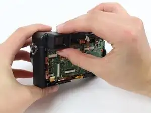
    • You may need to use tweezers and a spudger to disconnect some of the ribbon cables so they do not break.

    • Disconnect the nine visible ribbon cables/ZIF connectors by flipping the black bars up and pulling the ribbon straight out of the connector.

    • Disconnect two more cables in the upper left corner of the board, hidden behind the visible cables.

    • Learn more about disconnecting ZIF connectors here.

    All of these connectors have a backflip mechanism (a bar is flipped up to allow insertion or removal of the ribbon cable) except the smallest two. One is pictured in this photo second from left on top, and the other is hidden on the top underneath other cables. These two connectors have no locking mechanism. The cable is simply pulled directly out.

    Damon Schreiber -

    The step is fine but doesn't underline an important deal: when you have to put the cables back it's a nightmare. Be very very carefull putting them back in the original position. The most difficult are the second from left to the top as mentioned by Damon Schreiber in the former comment and another not underlined in the foto that is right close to the top of just mentioned.

    enrycone -

  12. 3Qx1hNYMbZE2os4e
    • Use a Phillips #000 screwdriver to remove the two 4.5 mm screws.

    • Use a Phillips #000 screwdriver to remove the 2.5 mm screw.

    The lengths shown for the screws didn’t match my camera. The upper two screws were shorter than the bottom screw in this step. The bottom screw had a coarser thread pitch since it’s screwed into plastic and the top two are screwed into metal.

    Nick Marshall -

    I experienced the same thing as Nick Marshall

    pinkerton.farm -

  13. NY1qhhmRLfuhGAIW
    NY1qhhmRLfuhGAIW
    OBh5Uh4WGLr3cDrV
    • Use two fingers to gently pull the viewfinder toward you and out of its housing.

    • The black plastic piece is still on the viewfinder in this image, but should have been removed during LCD screen removal.

  14. VVETkcfBCAIKkHKf
    VVETkcfBCAIKkHKf
    p3PZRH4ZTH4Piptq
    • Start at the top of the camera and use the plastic spudger to pry the motherboard out of the camera.

    on my model i had to pop out the plastic frame surround holding the flip out hdmi cover - until that was popped out the motherboard would not come - after though - easy as pie...

    Kevin Holmes -

    Yes, I would flip open the AV and HDMI cover and look at how the connectors sit. One is flush and one is a little below the surface. The plastic frame has tabs on the sides that lock into the camera shell. It’s probably best to pull the frame out with the motherboard.

    Nick Marshall -

  15. HXjfhn3q4CaIyfBZ
    HXjfhn3q4CaIyfBZ
    m32EFohB1H632YXY
    • Take the viewfinder you took out earlier and pull the small metal piece off of it.

  16. aC1LStmOCKMDBJXY
    aC1LStmOCKMDBJXY
    1WPdXbVuGAalSVCy
    • Pull the large metal piece off of the viewfinder.

  17. WJXcFlP2LZNb1oHe
    WJXcFlP2LZNb1oHe
    S6chABBAkPLsBXXU
    naFBMxNmo5HbOdSQ
    • Use a Phillips #000 screwdriver to remove the three 3.5 mm screws.

    • Use a Phillips #000 screwdriver to remove the three 3 mm screws.

    • In some models these may be T3 or T4 Torx screws.

    • Gently pull the copper plate towards you to remove it.

    • The sensor is attached to the copper plate and will come out with the copper plate. The thin, red glass plate glued to the front of the sensor is the infrared filter.

    The three 3mm screws are Torx for me. Now I have to find the right driver for this.

    Rincewind -

    The correct size is TORX T3

    bjdwyer -

    To clean the sensor is better not to remove from the lens. Remove the full objective and disassemble the back cover with sensor included and clean it. This avoids having to adjust the focal plane

    thunderiv -

    Did you happen to take pictures of this? I'm prepping to clean my LX100 sensor, and would love to see what you mean.

    andynease -

    please! show us how!, thank u very much!!!

    guidoost -

    Hey can you please show us the process of disassembling for sensor cleaning? Thanks!

    Laurent Gagné -

    Agree. Whole lens assembly with a sensor comes out after you remove the copper plate (first 3 screws). You don’t need to touch torx screws to remove it.

    Andrey Valentsov -

    how can i clean the sensor? explain it! thanks

    guidoost -

    The sensor is on the back of the copper plate shown in step 17. You’ll need a TORX T3 driver to remove the three “orange” screws and detach the plate. Once you get the copper plate removed you can clean the sensor. There is a wealth of information on how to actually clean the sensor once you can access it. Here is a link: http://www.howtogeek.com/162413/how-to-c...

    bjdwyer -

    Does anyone know what size Torx driver is needed for the three 3mm orange screws?

    bjdwyer -

    I used a T4 Torx driver to remove these screws on mine (I didn't have a T3 handy). Note that there are springs behind the copper plate directly underneath the Torx screws. Be careful not to lose these.

    Damon Schreiber -

    I also used a T4 torx screwdriver.

    Kevin Darras -

    Where do the 3 springs go back in? I can’t see anywhere obvious to put them.

    Adam Stiling -

    > Where do the 3 springs go back in? I can’t see anywhere obvious to put them.

    They go beneath the three “orange” screws in step 17.

    Note that these screws are used for adjustment of the focal plane of the sensor. To reset them to the original position, I put a small black mark with a permanent marker on each of the screws (take a photo after you did that) and then tightened them until I met some resistance. All three screws needed a different amount of rotation (1.3, 0.8 and 1.0 turns)

    After cleaning the sensor, I tightened the screws and then turned them back the amount I noted earlier.

    Stefan -

    Hello, after reassembly I have troubles with focusing. Obviously I didn’t tighten the torx screws correctly. Is there any way (method) to know how to tighten them correctly? I get an error “0.5m - ∞ “. Please help.

    Zao Pao -

    Stefan, unfortunately I messed up the first time I tried this and mixed up the screws, so my marks were in different spots. Can you be specific as to which screw location has each amount of rotation? Thank you!

    Jimmy -

    If you have to revome dust particles from the sensor, you may try first without removing it (do not unscrew the three Torx screws, which are fine-tuned for correct focusing). Just blow air through the holes (like the larger one in the right, where the Torx screw is), using a manual pump. This method worked for me, and mine was really contaminated.

    rfiumano -

    I needed to remove torx screws to access the sensor. (I got the lens assembly out by pushing on the front of the front-most lens, but it didn’t make accessing the sensor any easier so i recommend just leaving the lens assy in place. Less chance of bunging up ribbon cables too…) I did NOT need a torx tool, just a small enough flathead jeweler’s screwdriver. I marked the 3 screw locations 1,2,3. I marked the 12:00 position on all screws, then counted 1/2-turns needed to release each screw. I put each screw in it’s own egg-cup, along with the corresponding spring found under it. Made sure it all went back exactly the way it came out and had no problem. I used walgreens disposable pre-wetted microfiber lens wipes to clean the sensor with THE LIGHTEST touch I could- just dragging the wipe edge across the sensor…. no rubbing! used gloves to keep finger oils at bay. Dust illuminated by a strong side-light clearly was removed with one wipe. no residue and perfect results. GOOD LUCK!!

    Rick Sanger -

    Following the accurate guide and the additional remarks I managed to clean the sensor and reassemble my camera, thank you very much! Unfortunately, there is not enough room around the sensor plate to blow air through them, thus I had to remove the “orange torx screws“ to access the sensor directly. But BEFORE touching these screws I measured the copper plate position near the three screws by a digital indicator (with 1 micrometer precision) relative to a nearby position of the lens house. After cleaning the sensor (a few strong compressed air blows were sufficient) I tightened the orange screws to meet their original position. I managed to reassemble the sensor plate with about 10 micrometer precision. I made test images with US AF targets attached to a wall, and it seems that focusing is working correctly.

    Gábor Erdei -

  18. Mh3Ka2YZsS5XFInR
    • Use a Phillips #000 screwdriver to remove the 4 mm screw.

    • Use a Phillips #000 screwdriver to remove the 4.5 mm screw.

    • Use a Phillips #000 screwdriver to remove the five 3.5 mm screws.

    • Use a Torx T3 screwdriver to remove the three 3.1 mm screws.

    I have a later build and there are some slight differences. It is not necessary to remove the Torx screws

    jfranci3 -

    Actually you don’t need to unscrew ANY of these screws at all. After you remove 3 bolts which hold a copper plate (in front of sensor) the whole assembly can be removed from the camera. Sensor CAN stay at place.

    Andrey Valentsov -

  19. 4XsKVMXTsSZwluHK
    4XsKVMXTsSZwluHK
    WKbNjZ4w2VR3u335
    • Use a plastic spudger to gently pull the flash assembly out of its casing.

    • Gently pull the lens casing out of the camera.

    • Both the flash assembly and the lens casing will still be attached to the camera through ribbon cables so be careful not to rip them.

    • Be careful not to touch the leads on the capacitor, to avoid an electric shock.

    You can pull out the motor with the lens/sensor assembly. It is much easier this way.

    jfranci3 -

  20. IdfNvftwrQkPUXAt
    IdfNvftwrQkPUXAt
    XWRHrcavnuorkewr
    • With two fingers, pinch the edge of the lens and gently pull it out.

    • You may need to use a spudger here to lift an edge of the lens up and make it easier to grasp.

    I have a later build with plastic zoom gear. The focus lens seems to release with by hitting a level in the area where the two wires reach deep into the lens. Put your pry bar in there and feel for the release.

    jfranci3 -

  21. Hj6YVP2vcIfVbFsH
    Hj6YVP2vcIfVbFsH
    CGCkuGso3i5pL6rQ
    • Use a Phillips #000 screwdriver to remove the 4.5mm screw inside the lens housing.

    • Gently pull the top piece off the camera.

  22. 4IdNONEGvtaREXZV
    4IdNONEGvtaREXZV
    NvU2dMjYOqVjevGp
    xC6cMVheGLfOPbTw
    • Use a Phillips #000 screwdriver to remove all five 4.1mm screws from the piece you took off in the previous step.

    • Gently pull the metal cover until it turns 180 degrees.

    • The metal cover will not come all the way off because it will still be attached by ribbon cables.

  23. gS3jGIDALjt3XqA1
    gS3jGIDALjt3XqA1
    YhQhD2i3KVGbibXn
    GRXSduHptq6tpBgw
    • To remove a knob, remove the screws on the white piece underneath the knob you want to remove with a Phillips #000 screwdriver.

    • The left knob is being removed in this step but the process is the same for any of the knobs pictured in this step.

    • Pull the corresponding white piece off.

    • Flip the piece over and pull the corresponding black knob off the top of the camera.

  24. UO5N2RfLuAJyAuCM
    • You have completely disassembled your Panasonic Lumix DMC-LX100!

    Not yet. Show us how to disassemble the lens.

    Ronnie -

    The “Focusing Group” (round black part shown bellow the lens, attached to the zoom motor) will not come out of the lens assembly. There are no visible screws that hold it in place, but it does appear that is fastened in some way. Any advise how to disassemble it?

    ahpopov -

    Hi, I have this System Error (Focus) when I open the LX100. The camera fell and the lens got stuck, with the lens protruded even after turning it off. Help please?

    Thank you.

    LloydB

    yoyoy -

    Do you know the easiest way to remove the LX100 front panel? I want to replace the battery door.

    hellokk -

    I replaced the battery door by following steps 1 to 9, then the first stage of step 10. I managed to pull the display and the metal frame it sits on just far enough outwards to allow me to pull the battery door hinge pin out - I didn’t take the display off the frame or the frame completely off the mother board. Don’t let the door spring fall inside the camera when you take the hinge pin out. The hinge pin is surprisingly long.

    Make sure you read all the comments for step 9, as the screw beneath the thumb grip needs to come out before the back cover can be prised off with a spudger.

    Rog Hipkin -

Conclusion

To reassemble your device, follow these instructions in reverse order.

Sydney Dye

Member since: 12/01/16

1206 Reputation

35 comments

nice! can you do one for lx7 (leica dlux 6 even better)?

xania -

Thanks for the effort in compiling this, however even being pretty experienced in precision instrumentation and electronic repair but I encountered some difficulties.

1: To remove the hot shoe cover plate you actually have to lift on the 'forward' end of the plate nearest the lens to un latch and slide it out, not the "back end"

2: The screws are so tightly glued below the hot shoe that they are nearly impossible to remove, I got 3 out but the same front one that appears to be missing in your pictures is stuck fast. The screw that holds the LVF is also glued fast and I believe it's smaller then a 000 phillips.

3: The back metal plate does appear to be glued to the top of the body and no amount of prying seems to loosen it.

It appears Panasonic intended this camera to be disposable and not dissembled. Sad because all of them seem to get dust on the sensor at some point.

Shemp Howard -

Hello,

Thank you for the post.

I would love to add a microphone jack and cannot see the internal microphone wires. Are they part a ribbon (in which case ia m out of luck) or they are independent from a ribbon and accessible?
Reza Molavi -

Hello, I destroyed a wire, the one for the contraol panel (menu, qmenu, arrows, ...) Everything is working fine, but not key are working.

I need the wire to connect to the motherboard.

The ref is : STJ0060SW-9<-->1SW (and 3 special characters)

Where can I buy this ?

Or buy the right keyboard ?

rodyh2 -

When removing the sensor - what about the adjustment of it. Does the autofocus system has to be re-adjusted? As someone mentioned springs under the copper plate I'd assume they are to adjust the focus and simply reassemble all parts would lead to defocused state.

Anyone who did it already and can tell about focus working proper again?

Tom Göller -

I've completed this, and had no issues with focus. I hand tightened the screws when putting it back together and it focusing just fine!

Trigg Bowlin -

I had the same issue. I opened the camera again an reassemble it. It appears that the sensor was not level correctly and that made the camera unable to focus. My advice is to open it again and make sure the sensor is level and fits perfectly on the copper plate. Mine is working as good as new.

karin lizana -

I just removed a huge black spec near the centre of view from my sensor following these instructions - I haven't done a lot of testing beyond turning on the camera, checking the dust speck was gone, and the controls - but every thing seems fine so far.

Obviously I didn't go beyond step 17 - once I saw the offending dust boulder on the sensor.

In my model the sensor was not attached to the copper plate - it was screwed down separately with 3 torx T4 screws.

Be careful removing the sensor - there are 3 springs mounted underneath - I almost lost one - but they go back easily, and as I mentioned the sensor is screwed down with 3 torx screws - so @tomhh as I say only basic smoke tests so far, haven't looked at pictures on a large screen, only on the built in lcd, but autofocus and manual focus appears fine - focus peaking works too.

Also @shemp74 #2 and #3 did not apply to my camera; all screws came out easily, and copper plate under motherboard, and sensor under that, both came out just undoing screws.

Kevin Holmes -

I tried to follow these procedures to clean unsightly dust from an LX100 sensor. When prying off the back plate (step 8), it was very difficult to loosen the upper-right portion adjacent to the thumb grip. Wedge action was not enough. Some bending or warping was necessary.

When removing the copper plate and sensor (step 17), I saw that some of the philips screws had degraded or stripped heads that a fine screwdriver could turn only with great difficulty. One of the three spring screws holding the sensor would not budge. Another turned free, but later refused to re-tighten fully. I inserted a "canned air" straw through an open edge of the sensor / lens cavity to blow out dust.

Reassembly was dodgy. A tape connector ceased to stick. Ribbon cables resisted easy return to their clamps. Some screws could not tighten properly. Warping of the back plate left some small gaps and crooked screw settings.

Camera now dead. When turned on, the LCD now reads "System Error [Focus}." Lens stuck.

John Koch -

I have dust on the first element of the lens any way to remove just the first glass.

steve -

Wanted to remove dust from the sensor. Same issue as reported by John, when prying off the back plate, the top right corner would not come off without bending the frame. LCD now no longer working and still stuck with horrible dust spots.

Boudewijn Maten -

I dropped the camera and dislodged one of the lens elements. I can see a misplaced piece of it from the front glass. Is there any tutorial of disassembling the lens? I’ve taken apart the camera as per your guide. BTW, it’s an excellent guide.

Ronnie

Ronnie -

Also need help on putting the lens together. There’s a ball bearing that I don’t know where it goes… guess I didn’t pay attention during the disassembly.

mattwucn -

mattwucn, how did you take the lens apart? I can’t figure out how. I’ve removed the lens and looked at it from all angles, turned the gears manually but can’t figure out how to remove each lens frame units. There are 3 lens frame units interlocked with each other. I’ve watched YouTube videos of taking apart other Lumix camera lenses by lining certain pins and sliding them out. I can’t find any pins to line up in the LX100.

Ronnie -

Hi Matt, If I remember rightly the bearing works together with a very small spring to create the clicking sensation when turning the aperture ring. It also holds the ring in place.

After removing the aperture ring look carefully around the lens housing for a small hole. Once you find it, place the spring inside the hole and the bearing on top. Don’t put the bearing in the hole you might never get it out.

Then while balancing everything together, take the aperture ring and look on the inside for a series of notches. Carefully line them up with the bearing and click the whole thing back together.

Good Luck!

Damian -

Hi Damian. Did you take your lens apart? Can you show me how? Mine has one glass element misaligned after a hard drop. I’ve followed the guide here to take the camera apart. But I don’t know how to tear the lens down.

Ron.

Ronnie -

I took my camera apart to clean the sensor, I put it together again and everything is working fine. EXCEPT, when I press the image review button (one that loks like a play button). The camera hangs up and I can’t even turn it off without removing the battery.

Anyone know what might be the problem?

Jonas -

Thanks! I used these instructions to remove the hot mirror glass in front of the sensor to convert the camera to a full spectrum version. I really only wanted it for infrared, and that is what I got. I tested it with various IR filters in front of the camera and it looks great!

pinkerton.farm -

Do you have the English firmware?

Bob -

I just finish the whole operation of disassembling and cleaning the sensor.

After reassembling, everything is fine, and even if some dust are still inside the lens itself, cleaning the sensor just resolve 99% % of the dust problem i had from f/5 to f/16.

Everything is working perfectly, including the focus! happy :)

Thank you for this great tutorial,

Good luck to the next trying this!

Black Sunrise -

Hi

I spoke to a professional camera technician.

He said that the sensor is supported by springs. The screws are for alignment of the sensor to the lens focal plane. He said bespoke software was required to align the sensor . The symptom of misalignment is poor focus in one or more corners.

Darren -

I followed this guide together with the service manual I bought on Ebay. Excellent write-up !

I was able to clean the sensor from some dust and the camera is working excellent again. Before I removed the sensor, I put a black spot on each of the three screws (make sure to remember where you put the marks) and then tightened the screws until I met some resistance. By returning the screws to their original position (which required 0.8, 1.0 and 1.3 turns), I think I reset the alignment to the original position. Focus seems to be OK.

The service manual indeed says that special hard- and software is required to perform the alignment, which I don’t have access to. In my experience, alignment can be done without it. Anyway: any slight mis-alignment is much better to live with than dust on the sensor.

Stefan -

Thanks to OP !

i followed the instructions to clean the sensor.

han an obvious speck of dust inthe end.

Like Jonas in march the review button causes the camera to hang till i remove battery.

i will reseat the controller ribbon and report back

Cheers Michael Sandner

Michael Sandner -

Hi

Does anyone have details on changing the battery cover

Thanks in advance

Dave Ackery -

Hi all,

i have the same question.... How to remove the battery cover? Mine is broken and I have a new one..

SebastianM -

Hi ! I need to clean the sensor, but I would prefer not to remove all the electronic parts. Is it possible to get to the sensor from the lens ? is it recommendable ? Thank you !!

repiti -

Has anyone already fixed the jammed SD card mechanism of LX100?

The card always pops out of it. The camera works OK, however, it is very annoying.

Although this tutorial is great I cannot figure out if this is even possible!

Is this part accessible at all?

Thank you,

Milank -

great guide, before i start how far into the disassembly do i need to go to replace a broken battery door? Many thanks

Neil Mullins -

Sorry Neil, no answer from me but I do have the same question. Does anyone ever answer the questions. I also need to to replace a broken battery door. Such an easy thing to break and so easily visible and accessible, there must be an easier way to pull the pin & replace the battery door.

Please do respond, we would greatly appreciate this a simpler fix. May be Scotch Tape is the way to go!

William Clarke -

Thanks a lot. I did clean myself the sensor of my LX100. The zif connector disconnection manual helped a lot.

Watch out the little zif connectors under the view finder it’s easy to leave one under a plate when you re-assemble the camera

Step 8 to 9 the screw that suppose to hold the first plate in step 9 was screwed in a way that was holding the back of the camera and had to be unscrewed before step 8

I had to unglue the rubber square in the right top corner of the back to reach this screw. May be it has been put this way by several previous returns at a Panasonic camera repair

Step 17 the screw that hold the sensor are torx so make sure to have the right torx screw driver before starting (the smallest size).

Watch out the little springs that work whith each screw of the sensor !

24images -

Where can I find a replacement for the flash unit? The camera works great, other than the flash no longer fires. Thanks!

juan -

hi, thanks so much. I had 3 dusts on the sensor and now, it’s operation like a brand new one. David from France

David Nörtershäuser -

Hi, thanks for the tutorial. I am wondering if the battery door can be replaced without camera disassembly. Thank you!

vj ivanov -

BEWARE, READ THIS IN CASE OF PROBLEM WITH PRYING THE BACK PLATE OFF (STEP 8) I have encountered a very important difference between above guide and how my camera was assembled. The silver screw in step 9 goes through the thumbrest, therefore through the metal shim that covers the entire back of the camera. I guess I have a different revision LX100, but, no suffix after 'LX-100', no discernible difference on the outside to indicate different revision. Although, the keyboard bit (the wheel, D-PAD, all the buttons on the back are a part of the back cover, and go off with it (bonded with). Trying to disassemble 'my' revision following above guide to the letter will most likely end up with damaged parts and a lot of frustration. I am pretty well versed in camera and lens repair, therefore fasteners hidden under the trim are obvious to me, but not for everyone.

BEFORE STEP 8 REMOVE FASTENER UNDER THE RUBBER THUMBREST (PEEL IT BACK FROM THE LEFT SIDE (CLOSER TO THE <AF/AE LOCK> BUTTON).

itsek rosenbaum -