Introduction
Use this guide to replace the I/O board in your Dell Latitude 7410 laptop.
The I/O (input and output) board, or daughterboard, consists of the right side USB ports, the 3.5 mm headphone jack, and the SIM card reader. The board is also responsible for cellular connectivity and the speakers.
-
-
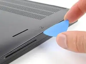
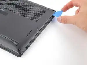
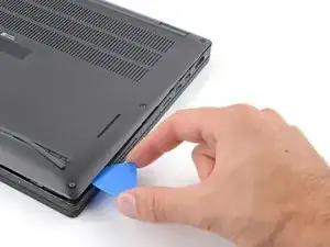
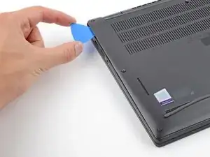
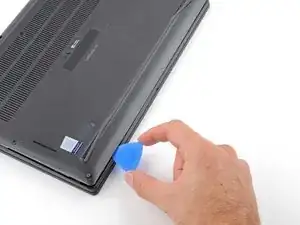
Insert an opening pick between the right edge of the back cover and the frame, just below the middle right screw.
-
-
-
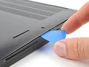
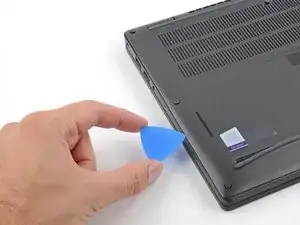
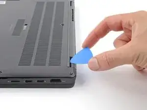
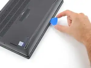
Insert your pick between the left edge of the back cover and the frame, next to the speaker cutout.
-
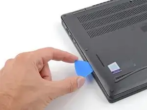
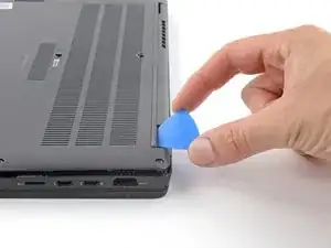
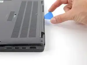
Slide your pick along the left edge to release the clips.
-
-
-
Insert your pick between the back cover and the right display-hinge to release the first clip along the back edge.
-
Slide your pick toward the left hinge until the second clip releases.
-
-
-
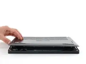
Insert your pick between the front edge of the back cover and the frame, just to the right of the bottom left screw.
-
Slide your pick toward the right edge until the front edge releases from the frame.
-
-
-
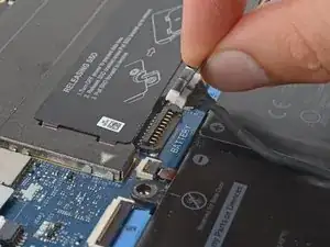
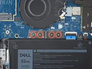
Grab the black pull tab on the head of the battery connector and pull straight up to disconnect it.
-
-
-
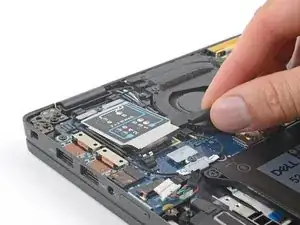
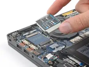
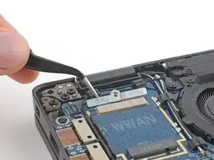
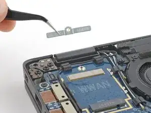
Use the flat end of a spudger to pry up the WWAN card cover from its clips on the I/O board.
-
Remove the cover.
-
-
-
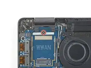
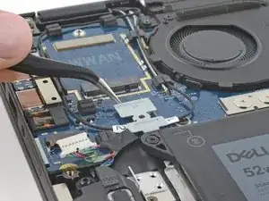
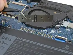
Use your Phillips screwdriver to remove the 3 mm screw securing the WWAN cable bracket.
-
Remove the cable bracket.
-
-
-
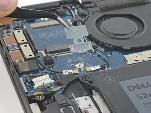
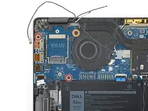
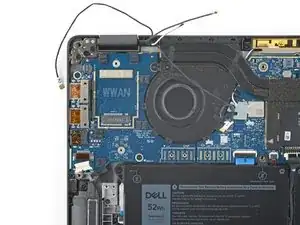
Use your Phillips screwdriver to remove the 3 mm screw securing the antenna cable bracket.
-
Remove the antenna cable bracket.
-
-
-
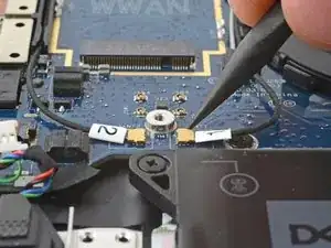
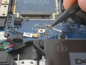
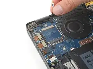
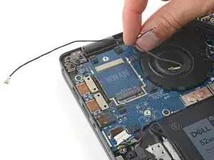
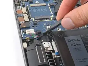
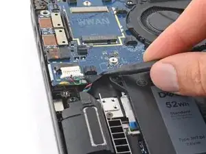
Use your spudger to disconnect the antenna press connectors labeled 1 and 2 by prying the heads of their connectors straight up.
-
-
-
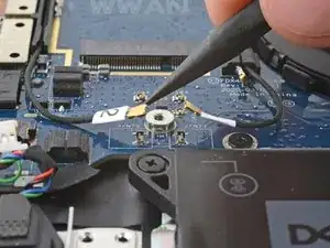
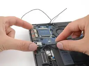
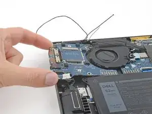
Lift the antenna cables out from their cable routing on the I/O board and move them away from the board.
-
-
-
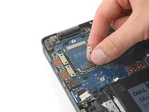
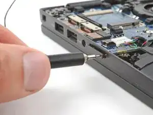
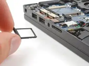
Insert a SIM card eject tool, bit, or straightened paperclip into the SIM eject hole.
-
Use your fingers to remove the SIM card tray.
-
-
-
Use your Phillips screwdriver to remove the four 4 mm screws securing the interconnect pad.
-
Use tweezers or your fingers to remove the pad.
-
-
-
Use your Phillips screwdriver to remove the three screws securing the I/O board:
-
Two 3 mm-long screws
-
One 3.5 mm-long screw
-
-
-
Insert the flat end of your spudger between the bottom edge of the I/O board and the frame.
-
Gently pry up until you can grab the left edge of the board with your fingers.
-
-
-
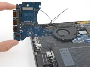
Grab the left edge of the I/O board.
-
Slide the board to the left until the top right screw mount clears the heatsink.
-
Remove the board.
-


To reassemble your device, follow these instructions in reverse order.
Take your e-waste to an R2 or e-Stewards certified recycler.
Repair didn’t go as planned? Try some basic troubleshooting, or ask our Answers community for help.