Introduction

Use this guide to replace a broken display assembly, or screen, on your Dell Latitude 7410 laptop.

  1. KVhJSEJn35pRtpTg
    • Allow your laptop's battery to drain below 25% before starting this repair—a charged battery may catch fire if damaged.

    • Unplug all cables, fully shut down your laptop, and close the lid.

  2. ZGA51OPDJSxC2TYs
    • Use a Phillips screwdriver to loosen the eight captive screws securing the back cover.

  3. FLbNUScF6GTmQtVF
    FLbNUScF6GTmQtVF
    4AGQckNfxEpKoEKU
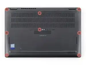
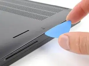
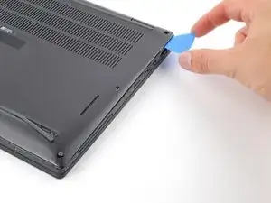
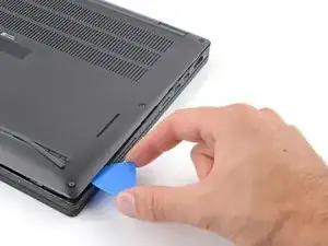
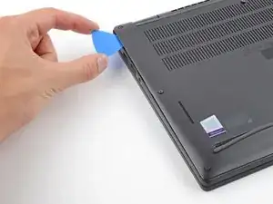
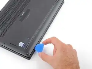
    • Insert an opening pick between the right edge of the back cover and the frame, just below the middle right screw.

  4. DTlPw2pqGIDkkYOf
    DTlPw2pqGIDkkYOf
    CUuCmdhYkBXTfkN2
    • Slide your pick along the right edge to release the clips securing the back cover.

  5. 1OHWpDCm1cXCoZYp
    1OHWpDCm1cXCoZYp
    slJJSckwBnuAAYor
    PYsuRNtnNHwJ6wCv
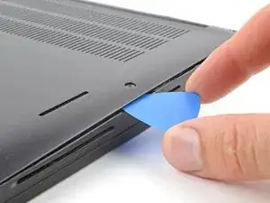
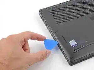
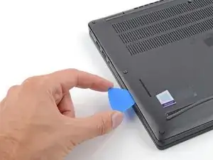
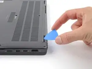
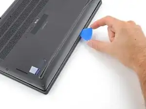
    • Insert your pick between the left edge of the back cover and the frame, next to the speaker cutout.

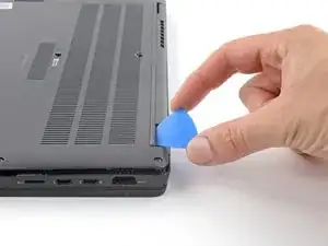
    • Slide your pick along the left edge to release the clips.

  6. x65QutnMkQPYHDWq
    x65QutnMkQPYHDWq
    XtCFfNqCafBooWsj
    UePh1xVQ2ittXubl
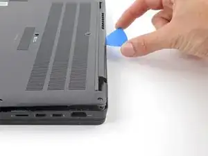
    • Insert your pick between the back cover and the right display-hinge to release the first clip along the back edge.

    • Slide your pick toward the left hinge until the second clip releases.

  7. qcvfJR5d3mXGNSqY
    qcvfJR5d3mXGNSqY
    EV6QgyotJEQ2Irhk
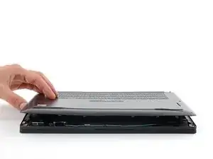
    • Insert your pick between the front edge of the back cover and the frame, just to the right of the bottom left screw.

    • Slide your pick toward the right edge until the front edge releases from the frame.

  8. oXxrAtcp2JqMPOsF
    oXxrAtcp2JqMPOsF
    GpA6xUysqbjJU5Fr
    • Remove the back cover.

  9. TyeDs4aNSeeQOfTG
    TyeDs4aNSeeQOfTG
    6VSAPrDuD1m6mYjw
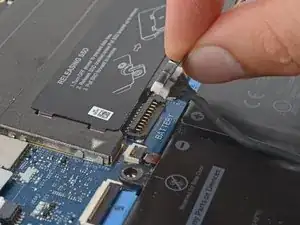
    • Grab the black pull tab on the head of the battery connector and pull straight up to disconnect it.

  10. 1MsTNoGoMEmsVVGA
    1MsTNoGoMEmsVVGA
    5tI4IH2JV4RoMwhj
    6asEvvFpnYe6gu2R
    • If your laptop doesn't come with a WWAN card, skip the next two steps.

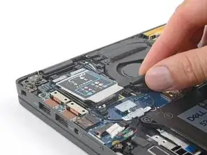
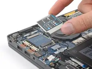
    • Use the flat end of a spudger to pry up the WWAN card cover from its clips on the I/O board.

    • Remove the cover.

  11. NPo5mXebMlME2oat
    NPo5mXebMlME2oat
    dJGQMYSYMuuBuVt6
    n36qB5c4WISKKlJ6
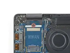
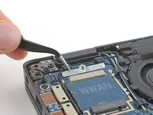
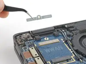
    • Use your Phillips screwdriver to remove the 3 mm screw securing the WWAN cable bracket.

    • Remove the cable bracket.

  12. DxRRm6eUJGrxnmyI
    DxRRm6eUJGrxnmyI
    uegXa2RYtH5CUci1
    hBbIsOm4K4h1BpJW
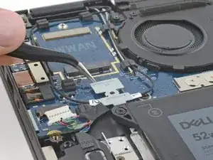
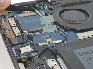
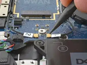
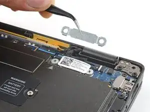
    • Use your Phillips screwdriver to remove the 3 mm screw securing the antenna cable bracket.

    • Remove the antenna cable bracket.

  13. ifNYMSVJ6KN21TWQ
    ifNYMSVJ6KN21TWQ
    ZpNC5ar6HgWVRwwT
    cuYV1TyhDe1FegSU
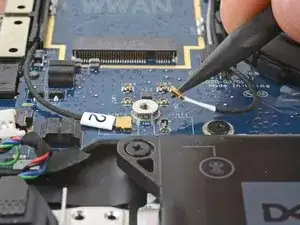
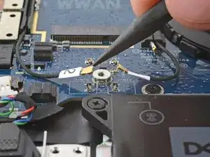
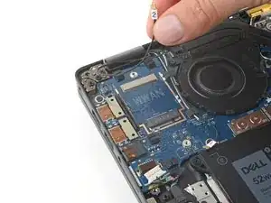
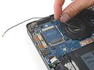
    • Use your spudger to disconnect the antenna press connectors labeled 1 and 2 by prying the heads of their connectors straight up.

    • To re-attach press connectors, carefully align and press down on one side until it clicks into place, then repeat on the other side. Don't press down in the middle. If the connector is misaligned, the pins can bend and cause permanent damage.

  14. 3aHrkPQRqauSCrTo
    3aHrkPQRqauSCrTo
    aiulFCbFFZcitlgb
    MysuAIKYmWlVJDlX
    • This step shows a laptop that didn't come with a WWAN card. If yours has one, disconnect and remove it now.

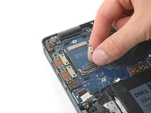
    • Lift the antenna cables out from their cable routing on the I/O board and move them away from the board.

  15. wN1DVxBKqjvJcJcW
    wN1DVxBKqjvJcJcW
    IAXTTNuOic1vetZm
    uPYHpneXBOFLfvMD
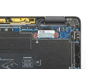
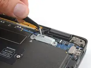
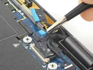
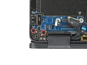
    • Use your Phillips screwdriver to remove the two 2.7 mm screws securing the display cable bracket.

  16. sPfXWNmFwHRBSwHs
    sPfXWNmFwHRBSwHs
    mWQwftPNZZtxZYYC
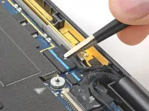
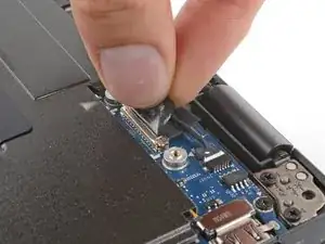
    • Use tweezers or your fingers to disconnect the leftmost wide connector by pulling it straight out of its socket.

  17. YSCuajcv5E1XoUF4
    YSCuajcv5E1XoUF4
    hAjPJbo1rJsoyaJ6
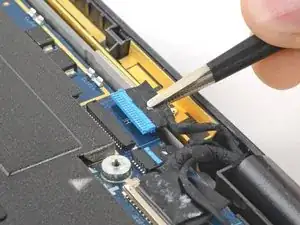
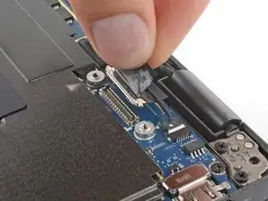
    • Use tweezers or your fingers to disconnect the narrow connector, just to the right of the previous connector, by pulling it straight out of its socket.

  18. Zkfyhl4efriMA11F
    Zkfyhl4efriMA11F
    LpOjxVQdHPVAlc5w
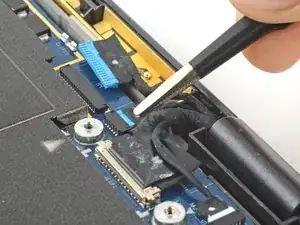
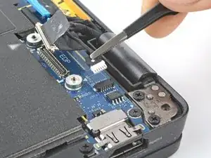
    • Use your fingers to grab the display connector pull tab and pull straight up to disconnect the display.

    • During reassembly, reconnect this cable before the two leftmost connectors.

  19. iWZTrcoVKCOHORAM
    iWZTrcoVKCOHORAM
    aNIVBhUBrEfOeSr6
    • Use tweezers or your fingers to disconnect the camera connector by pulling it straight out of its socket.

  20. 6e11cXlZuVnPFKIq
    6e11cXlZuVnPFKIq
    4liL4O1nMOn65xV5
    • Grab the body of the laptop and open it 90 degrees.

  21. dlxvywABnkxKjuWb
    • Lay the laptop keyboard-side-down over the edge of a table with the display hanging below.

  22. ISnAEoLb1lXeJtiA
    ISnAEoLb1lXeJtiA
    BApEAxvl4cT5nTXr
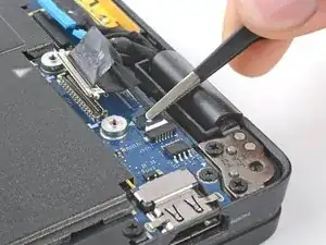
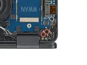
    • Use your Phillips screwdriver to remove the four 5.7 mm screws securing the hinges—two on each hinge.

  23. EwBSSgLaFajJPRPv
    EwBSSgLaFajJPRPv
    HBLywnQQkUjhc2cA
    • Be careful not to catch on any cables hanging off the display assembly.

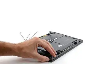
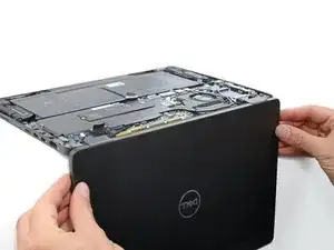
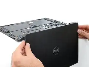
    • Grab the display near the hinges and lift it straight up to free the hinges from the frame.

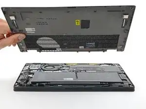
    • Remove the display assembly.

    Hi, once the display is removed how do I replace the back cover of the display?

    Thanks

    Bobby Iveson -

Conclusion

To reassemble your device, follow these instructions in reverse order.

Take your e-waste to an R2 or e-Stewards certified recycler.

Repair didn’t go as planned? Try some basic troubleshooting, or ask our Answers community for help.

Clay Eickemeyer

Member since: 19/09/22

65190 Reputation

0 comments