Introduction
This guide shows you how to install the logic board that controls the flash.
-
-
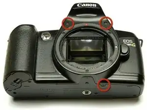
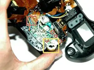
Using a #00 Phillips screw driver, remove three 4.4 mm Phillips screws as indicated by the red circles.
-
-
-
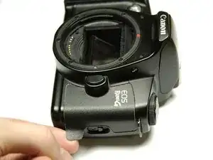
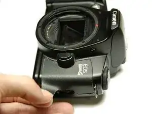
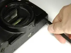
Using the flat end of a spudger, loosen the connection between the front panel and the device.
-
Remove the front panel using your hands.
-
-
-
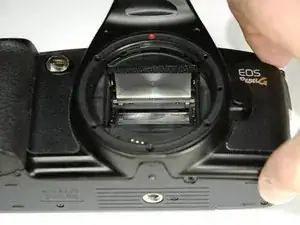
Turn Camera over.
-
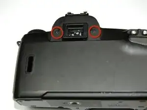
Using a #00 Phillips screw driver, unscrew the two 4.9 mm Phillips screws located on either side of the viewfinder.
-
-
-
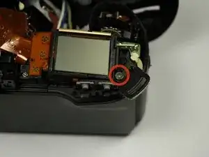
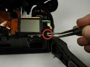
Using a #00 Phillips screw driver, unscrew the one 5.7 mm Phillips screw located next to the LCD screen.
-
-
-
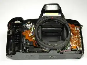
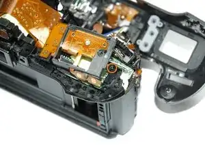
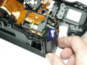
Lay the camera on its back.
-
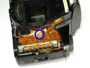
Unsolder the flash connection from the motherboard as noted by the blue circle.
-
-
-
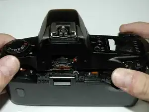
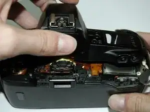
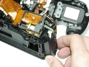
Remove the top panel by lifting it from the back, pushing it forward over the camera and letting it rotate down in front of the camera.
-
-
-
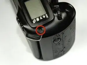
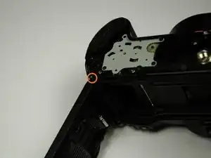
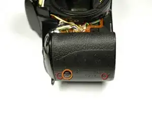
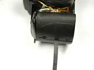
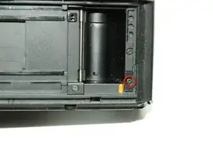
Using a #00 Philllips screw driver, unscrew the 6.8 mm Phillips screw that holds the strap anchor noted by the red circle.
-
Remove the strap anchor.
-
-
-
Unlatch the back panel.
-
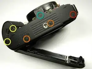
Using a #00 Phillips screw driver, unscrew the six screws on the bottom of the camera.
-
One 7.4 mm Phillips screw
-
Two 6.0 mm Phillips screws
-
Two 4.4 mm Phillips screws
-
One 3.9 mm Phillips screw
-
-
-
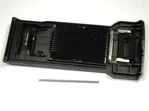
From the bottom of the camera push the hinge rod in with your finger.
-
Return the camera to its upright position.
-
Use pliers (or tweezers) to pull the rod out from the top.
-
-
-
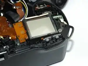
Using a 00 Phillips screw driver, unscrew the two 4.9 mm Phillips screws. on the inside of the camera.
-
-
-
Using a 00 Phillips screw driver, unscrew the two 4.3 mm Phillips screws on the side of the camera.
-
Use your fingers to pull out the plug that is located between the screw holes.
-
-
-
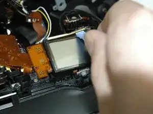
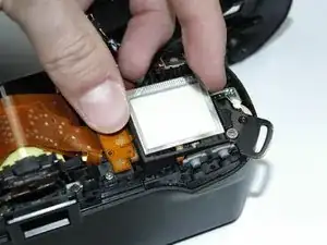
Pry off the small metal brace holding the LCD screen. (Push forward and slide toward the center)
-
-
-
Using a 00 Phillips screw driver, unscrew the 7.4 mm Phillips screw on the top of the camera.
-
Using a 00 Phillips screw driver, unscrew the 4.9 mm Phillips screw on the top of the camera.
-
-
-
Using a 00 Phillips screw driver, unscrew the 4.9 mm Phillips screw on the back of the camera.
-
Using a 00 Phillips screw driver, unscrew the 5.8 mm Phillips screw on the top of the camera.
-
-
-
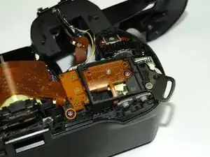
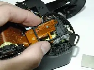
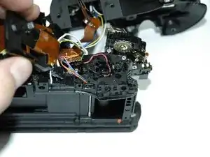
Use an Exacto knife to cut the white calking on the side of the side panel
-
Pull the side panel away from the camera.
-
-
-
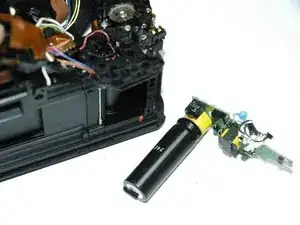
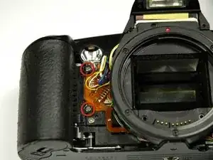
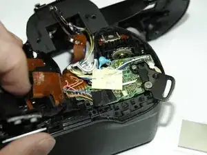
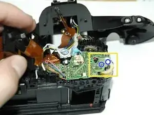
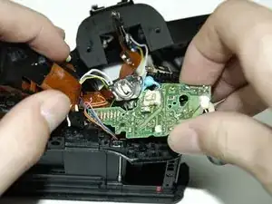
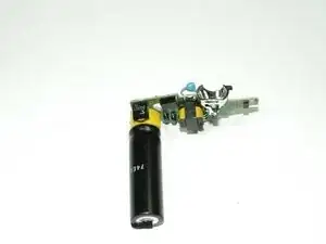
The large cylindrical object on the right side of the board is the flash capacitor.
-
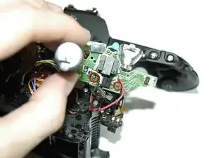
Touching the circuit board while the capacitor still holds its charge may result in a painful electric shock that you will long remember.
-
To make the board safe to work on, short out the two marked terminals with a capacitor discharge tool or the blade of a screwdriver or similar implement (with an insulated handle!) You might have to use moderate pressure to punch through the white goop that covers one of the terminals.
-
There might be little sparks and/or an audible pop. Be careful not to short other solder connections nearby.
-
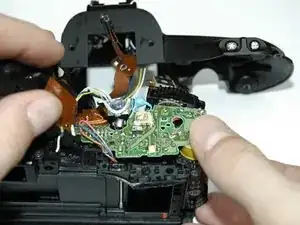
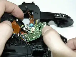
Unsolder all of the wires on the top of the logic board.
-
To reassemble your device, follow these instructions in reverse order.