Introduction

Use this guide to replace or upgrade one or both the M1 and M2 macro buttons on your Asus ROG Ally.

  1. vqjOL4ArFHFYnWRd
    vqjOL4ArFHFYnWRd
    R35152aPXbWqJyIE
    RNWYTLOLBduXfPut
    • Let your device's battery drain below 25% before starting this repair—a charged lithium‑ion battery may catch fire if damaged.

    • Completely power off your device and unplug all cables.

    • Consider laying your device on a soft cloth to prevent scratching or damaging the screen during your repair.

  2. IIaUFJ63RLGmQ4Ui
    IIaUFJ63RLGmQ4Ui
    G1oNRVqSWLPJQuue
    • Throughout this repair, keep track of each screw and make sure it goes back exactly where it came from.

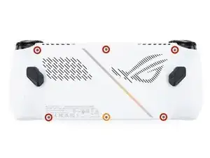
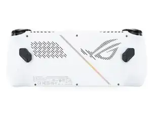
    • Use a Phillips #0 screwdriver to remove the five 17.2 mm‑long screws securing the top edge and bottom corners of the back cover.

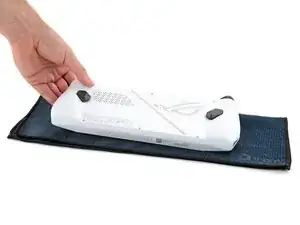
    • Use a Phillips #0 screwdriver to fully loosen the remaining captive screw at the center of the bottom edge. This should create a small gap between the back cover and chassis.

    • Don't try to remove this screw.

  3. huPyGW1EUkBGsSTE
    huPyGW1EUkBGsSTE
    M6IvvHetKHCpTy4U
    qi5vI6QX1xftg3B1
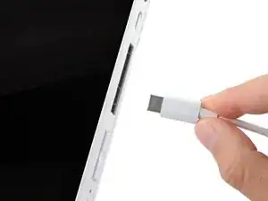
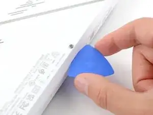
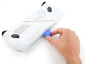
    • Insert the flat edge of an opening pick between the bottom edge of the back cover and chassis, near the captive screw.

    • Angle the pick upward and push it under the back cover.

  4. fFjsjRQ13SIhxyu3
    fFjsjRQ13SIhxyu3
    lY53VEwZPpoX4qpK
    q2nIrM1nNHBw6RmS
    • Plastic clips secure the perimeter of the back cover. You should feel and hear them release during this step.

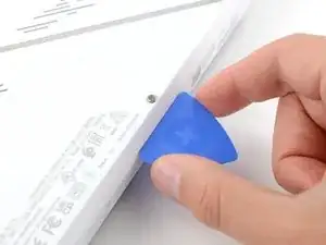
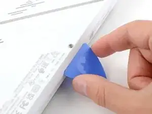
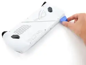
    • Slide the opening pick along the bottom edge and around the corners of the back cover to release the clips securing it.

    • Keep the pick at an upward angle under the back cover to help release the clips.

  5. ahsmjIA4qJNspYWG
    ahsmjIA4qJNspYWG
    B5LPMX4LkZDJYRC3
    TZXfUcBeqUFOe1ZG
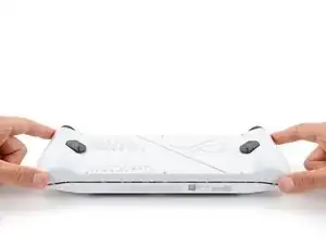
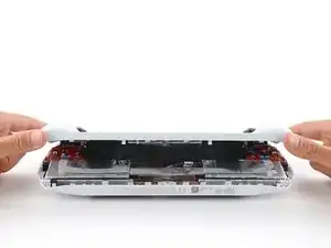
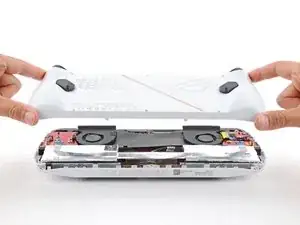
    • Lift the bottom edge of the back cover off the chassis to release the remaining clips.

    • Remove the back cover.

    • During reassembly, lay the back cover onto your device and firmly push down around the perimeter to engage the clips.

  6. hdXRgeFYfuvgO4bM
    hdXRgeFYfuvgO4bM
    GgM4uRqnuYJpqYOm
    • When removing the screws, be careful not to lose the springs under them. They can easily eject!

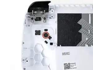
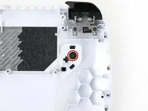
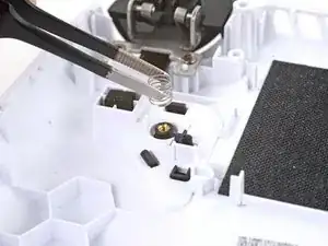
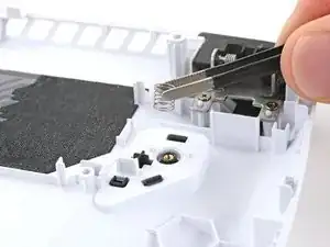
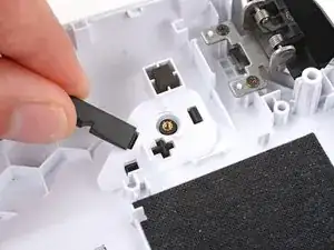
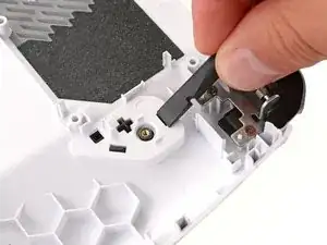
    • Use a Phillips #000 screwdriver to remove the 2.9 mm‑long screw securing each macro button (two total).

  7. 4iUquLFoXNOEJ4QA
    4iUquLFoXNOEJ4QA
    OKOEt4LkDli6xFFi
    oFQkslRPkFNVqQYm
    • Use tweezers or your fingers to remove the springs from their screw posts.

  8. r6nIrKBiVMxFGmq2
    r6nIrKBiVMxFGmq2
    Ahq2KlEjwdRsNVyj
    UUBtU3ptUUmYwSKV
    • Two rectangular clips secure the macro buttons to the back cover.

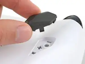
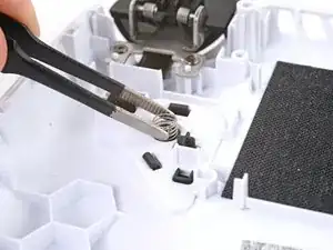
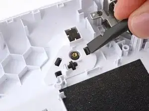
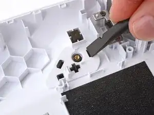
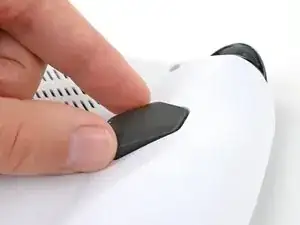
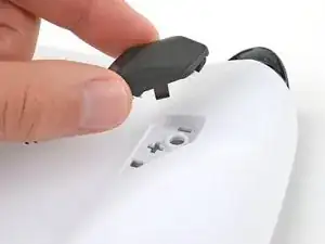
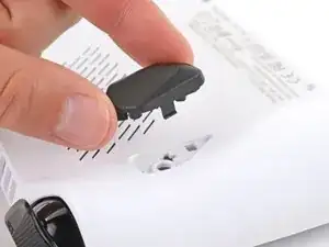
    • Use the flat end of a spudger or your fingers to push in the clips securing one of the macro buttons.

  9. ugbJXClXlYbZYg2w
    ugbJXClXlYbZYg2w
    JQ1MIkTHbPObW6jj
    • Remove the macro button.

  10. GLKuqPE3XHURdZp3
    GLKuqPE3XHURdZp3
    54DlVrxvtLbnp3tG
    • Repeat the last two steps to unclip and remove the other macro button.

    • During reassembly, firmly push the macro buttons into place to engage their clips. You should feel the clips click as they engage.

Conclusion

To reassemble your device, follow these instructions in reverse order.

Repair didn’t go as planned? Try some basic troubleshooting, or ask our Answers community for help.

Spencer Day

Member since: 14/09/22

49372 Reputation

0 comments