Introduction
I couldn't find a guide so I made my own for future reference. This repair only cost me twenty dollars as I found a cheap Touch Bar which ended up working great. My Touch Bar had the white light flickering when idle problem, so I decided to replace it. This completely fixed the issue.
In order to access the Touch Bar you will first need to remove the motherboard, and I advise also removing the Touch ID sensor to protect it from any damage when removing the glued Touch Bar. You might want to remove the screen to protect it, especially because you will anyway need to loosen a few of the hinge screws blocking access to the Touch Bar board. However, I chose not to remove the screen because I didn't have small enough Torx screw drivers for some of the antenna screws. There was however still one single screw(holding the Touch Bar board at the very end of the guide) smaller than the T3/4/5 that I had available, but I managed to remove this screw with a simple knife tip.
Keep track of every part you remove and especially every screw, they all have specific lengths and in the end you have about two dozen so if you mix them up you might end up completely stuck.
Be advised that although I have experience replacing screens and batteries, this was difficult and long for me, because of the final Touch Bar removal step where the Touch Bar was so glued to its slot that I had to scrape it bit by bit out. Not fun, but doable in time and with care.
Please comment if anything is incorrect, I might have made a mistake in what I wrote here compared to how I actually got it to work.
-
-
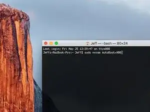
Power on your Mac and launch Terminal.
-
Copy and paste the following command (or type it exactly) into Terminal:
-
'sudo nvram AutoBoot=%00
-
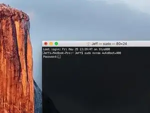
Press [return]. If prompted, enter your administrator password and press [return] again. Note: Your return key may also be labeled ⏎ or "enter."
-
sudo nvram AutoBoot=%03
-
-
-
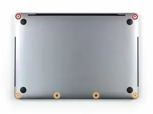
Use a P5 Pentalobe driver to remove the six screws securing the lower case:
-
Two 6.2 mm screws
-
Four 3.4 mm screws
-
-
-
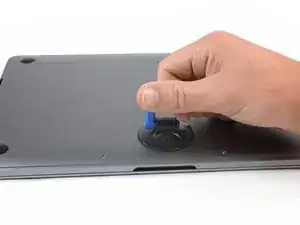
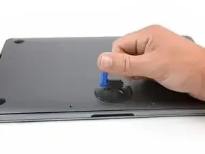
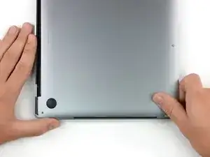
Apply a suction handle to the lower case near the front-center area of the MacBook Pro.
-
Lift the suction handle to create a slight gap between the lower case and the chassis.
-
-
-
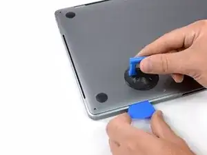
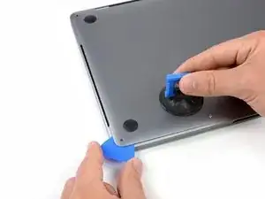
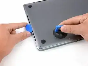
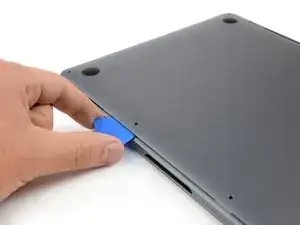
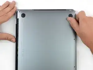
Insert one corner of an opening pick into the space between the lower case and the chassis.
-
Slide the opening pick around the nearest corner and halfway up the side of the case.
-
-
-
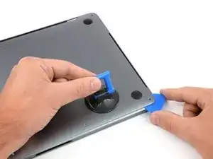
Repeat the previous step on the opposite side, sliding your opening pick under the lower case and up the side to pop the second clip free.
-
-
-
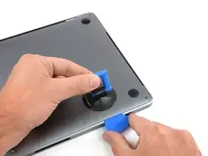
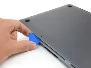
Insert your opening pick once again under the front edge of the lower case, near one of the two centermost screw holes.
-
Give the pick a firm twist to pop free the third clip securing the lower case to the chassis.
-
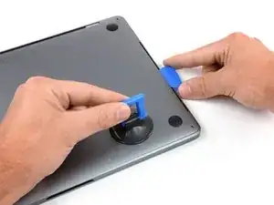
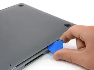
Repeat this procedure near the other of the two centermost screw holes, popping the fourth clip free.
-
-
-
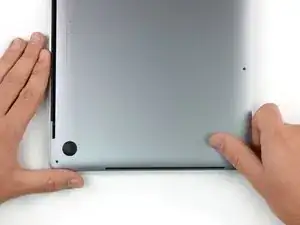
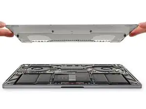
Pull the lower case firmly towards the front of the MacBook (away from the hinge area) to separate the last of the clips securing the lower case.
-
Pull first at one corner, then the other.
-
-
-
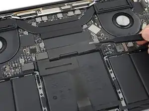
Carefully peel up the large piece of tape covering the battery connector, on the edge of the logic board nearest the battery.
-
Remove the tape.
-
-
-
Disconnect the battery board data cable by sliding it out from its socket.
-
Slide parallel to the logic board, in the direction of the cable.
-
-
-
Use a T5 Torx driver to remove the 3.7 mm pancake screw securing the battery power connector.
-
-
-
Use a spudger to gently lift the battery power connector, disconnecting the battery.
-
Lift the connector high enough so that it stays separated from its socket. If it accidentally makes contact during the course of your repair, it could damage your MacBook Pro.
-
-
-
Use a T3 Torx driver to remove the two 1.8 mm screws securing the trackpad cable connector bracket.
-
-
-
Use a spudger to disconnect the trackpad ribbon cable by gently prying its connector straight up from the logic board.
-
-
-
Carefully peel back the black tape to reveal the ZIF connector.
-
Unlatch the ZIF connector by flicking the arm on the connector upwards and carefully remove the cable from the connector by sliding it out.
-
Repeat this process with the newly revealed connector.
-
-
-
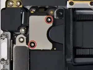
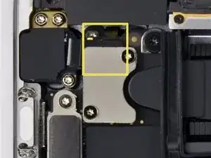
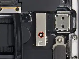
Use a T3 Torx driver to remove the two screws.
-
Once the screw have been removed carefully remove the metal shield.
-
Under the metal shield there is a connector, carefully unplug it.
-
-
-
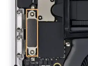
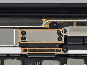
Use a T4 Torx driver to remove the two screws.
-
Two T4 Torx screws.
-
Carefully remove the metal shield.
-
The second cable you will disconnect will be lightly adhered so carefully slide a plastic spudger under it and finally unplug it.
-
-
-
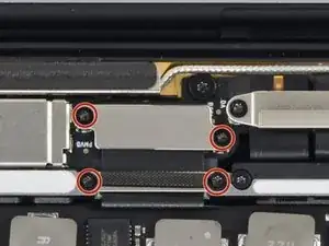
Use a T3 Torx driver to remove the four screws.
-
4 T3 Torx screws.
-
Once the screws are removed carefully remove the metal shields.
-
Carefully unclip the connector.
-
-
-
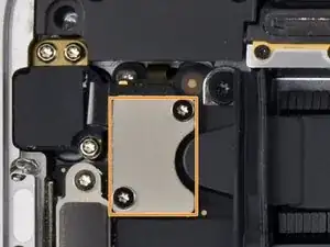
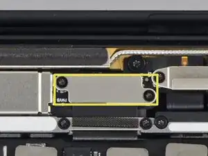
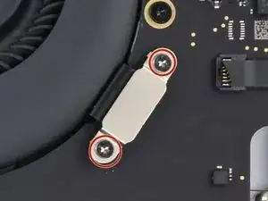
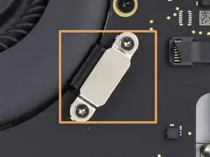
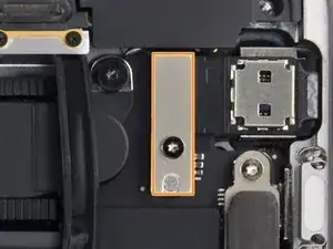
Use a T3 Torx driver to remove the two screws.
-
Remove the metal shield carefully.
-
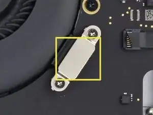
Carefully unplug the connector.
-
-
-
Carefully peel back the black tape to reveal the ZIF connector.
-
Unlatch the ZIF connector by flicking the arm on the connector upwards and carefully remove the cable from the connector by sliding it out.
-
Repeat this process with the newly revealed connector.
-
-
-
Carefully peel back the black tape to reveal the ZIF connector.
-
Unlatch the ZIF connector by flicking the arm on the connector upwards and carefully remove the cable from the connector by sliding it out.
-
-
-
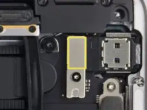
Use a T3 Torx driver to remove the two screws.
-
Once the screw have been removed carefully remove the metal shield.
-
Under the metal shield there is a connector, carefully unplug it.
-
-
-
Use a T4 Torx driver to remove the screw.
-
T4 Torx screw.
-
Remove the metal shield carefully.
-
Carefully unplug the connector.
-
-
-
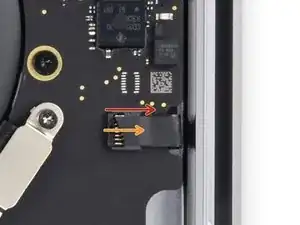
gently disconnect the audio socket flex cable with a spudger.
-
gently disconnect the Touch ID flex cable with a spudger.
-
-
-
Use a T3 Torx driver to remove the two 2.4mm screws securing the display cable bracket.
-
Use a T3 Torx driver to remove the two 1.2mm screws securing the display cable bracket.
-
-
-
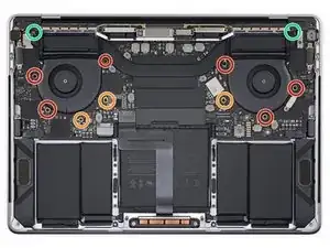
Use a T5 Torx driver to remove the six 2.2mm screws securing the logic board.
-
Use a T3 Torx driver to remove the three 1.9mm screws securing the logic board.
-
Use a T5 Torx driver to remove the two 2.3mm (3.7mm head) screws securing the heatsink.
-
-
-
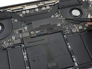
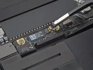
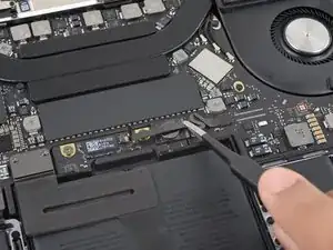
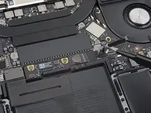
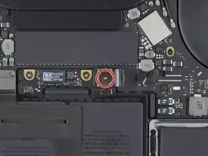
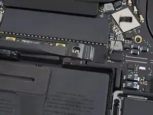
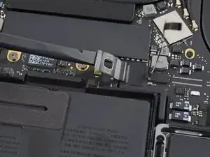
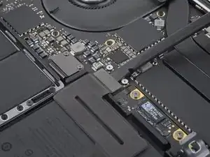
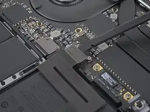
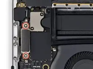
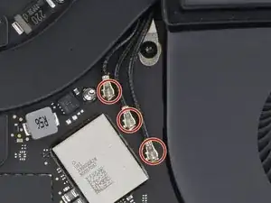
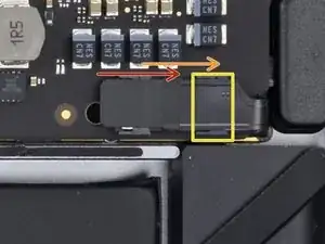
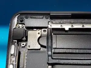
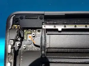
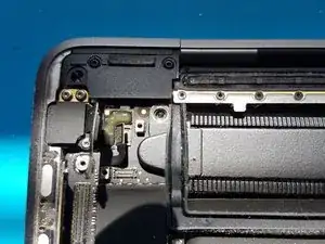
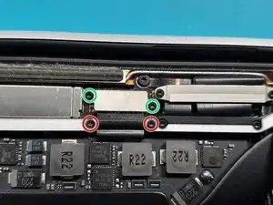
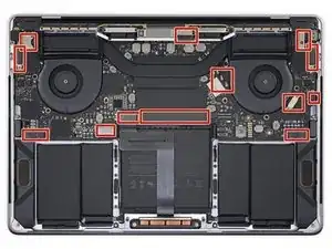
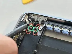
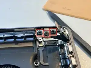
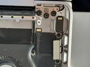
In red you can see the two connectors for the Touch Bar. We will need to remove other parts first to be able to free them and be able to install the new connectors.
-
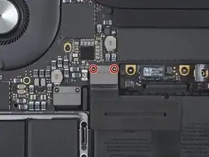
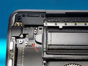
In green one notable screw that you need to remove because the board it holds in place prevents the Touch Bar connectors from exiting/entering through the main case of the MacBook.
-
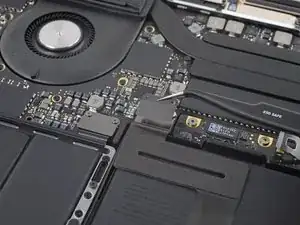
We will therefore need to unplug both connectors, and remove the board, which takes a few additional steps that follow below.
-
-
-
This is not strictly required. However I found when removing the Touch Bar that it necessitated a lot of scraping and force near the Touch ID sensor, thus I advise removing it for protection.
-
It is quite easy to remove, just be careful with the flex cable as it seems very fragile.
-
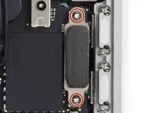
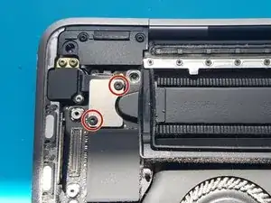
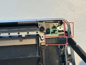
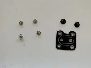
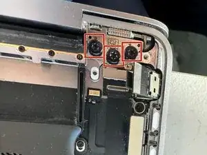
Remove the 4 red screws
-
Remove the 2 green screws
-
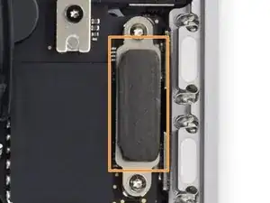
Remove the black bracket which is now free
-
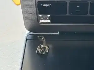
Carefully open the laptop lid with the screen at the bottom. The Touch ID sensor should free itself and stay on the screen.
-
-
-
This is necessary in order to remove the Touch Bar board and screw
-
Loosen the 3 T8 screws of the screen hinge
-
Be careful not to completely remove those screws
-
Be careful to be very gentle with the hinge from then on not to exert too much force on the cables going through the hinge axis !
-
-
-
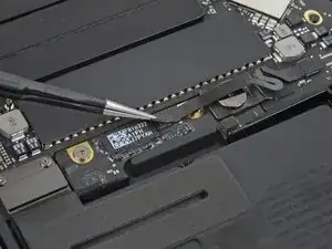
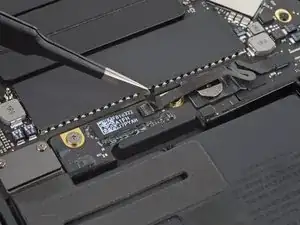
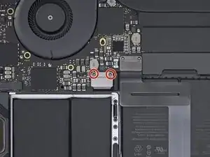
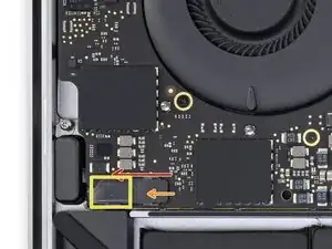
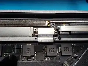
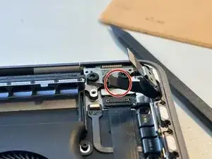
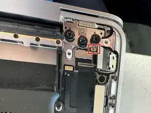
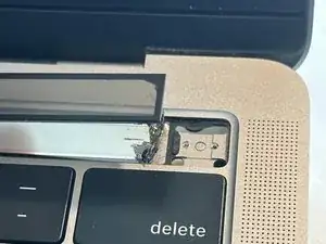
Remove the red screw half hidden between the screen hinge (I already removed it in the picture)
-
This screw is smaller than T3 but I used a knife tip because I didn't have such a small screwdriver.
-
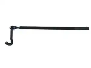
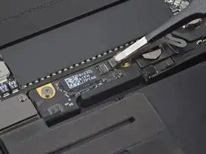
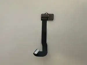
Then remove the Touch Bar board and its flex cable, they have some adhesive so be careful. The Touch Bar connectors are now freed to pass through and out of the main case !
-
-
-
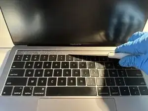
Thanks to the removal of the Touch ID sensor, we have some room to get under the Touch Bar to remove it.
-
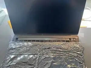
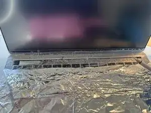
Seeing how messy the next steps got for my, I adise taping over the bottom of the screen and top of the keyboard to prevent any dirt bits getting stuck there. I put some tin foil over the rest of the keyboard but a paper or plastic sheet would be better.
-
I used a flathead screw driver but at first only the top glass popped off.
-
In the end I tried using an adhesive dissolver fluid, some thin spudgers, some fishing wire, but only brute force and the flat head screwdriver really solved it.
-
Please wear gloves and glasses as there are many glass shards flying about.
-
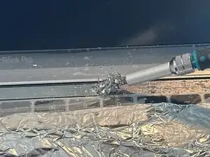
Keep scraping slowly but with force. This part took me about an hour.
-
-
-
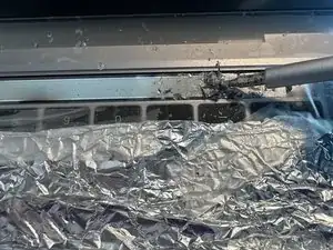
After finally removing the brunt of the Touch Bar material, I could remove the connectors going through the main body.
-
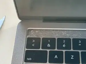
I spent some time scraping the remainders and the glue with different tools. Using a knife worked best, while being careful not to get injured or damage the screen.
-
The Touch Bar slot was somewhat scratched but in the end it didn't matter after installing a new Touch Bar.
-
-
-
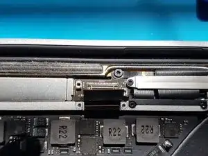
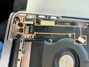
When completely removed, the Touch Bar connector body passthrough is clearly visible from the top and bottom.
-
Contrats, you have removed your Touch Bar !
-

Now put in your new Touch Bar, make sure when installing it that the Touch ID sensor still fits. You can reinstall the Touch ID sensor first, so the Touch Bar is better aligned when you adhere it.
Make sure it is well adhered in its slot, then follow the instructions in reverse order to reassemble the rest of the laptop !