Depth:7 (logarithmic), 18x AND, 6x OR, 7x XOR, 31 gates (linear)
Let me calculate the digit sum in base four, modulo three:
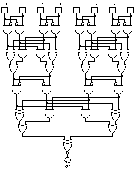
circuit drawn in Logisim
Generalisation, formally (hopefully somewhat readable):
balance (l, h) = {
  is1: l & not h,
  is2: h & not l,
}

add (a, b) =
  let aa = balance (a.l, a.h)
      bb = balance (b.l, b.h)
  in  { l:(a.is2 & b.is2) | (a.is1 ^ b.is1),
        h:(a.is1 & b.is1) | (a.is2 ^ b.is2)}

pairs [] = []
pairs [a] = [{h:0, l:a}]
pairs [rest.., a, b] = [pairs(rest..).., {h:a, l:b}]

mod3 [p] = p
mod3 [rest.., p1, p2] = [add(p1, p2), rest..]

divisible3 number =
  let {l: l, h: h} = mod3 $ pairs number
  in  l == h
now in english:
While there are more than two bits in the number, take two lowest pairs of bits and sum them modulo 3, then append the result to the back of the number, then return if the last pair is zero modulo 3. If there is an odd number of bits in the number, add an extra zero bit to the top, then polish with constant value propagation.
Appending to the back instead of to the front ensures the addition tree is a balanced tree rather than a linked list. This, in turn, ensures logarithmic depth in the number of bits: five gates and three levels for pair cancellation, and an extra gate at the end.
Of course, if approximate planarity is desired, pass the top pair unmodified to the next layer instead of wrapping it to the front. This is easier said than implemented (even in pseudocode), however. If the number of bits in a number is a power of two (as is true in any modern computer system as of March 2014), no lone pairs will occur, however.
If the layouter preserves locality / performs route length minimisation, it should keep the circuit readable.
This Ruby code will generate a circuit diagram for any number of bits (even one). To print, open in Logisim and export as image:
require "nokogiri"

Port = Struct.new :x, :y, :out
Gate = Struct.new :x, :y, :name, :attrs
Wire = Struct.new :sx, :sy, :tx, :ty

puts "Please choose the number of bits: "
bits = gets.to_i

$ports = (1..bits).map {|x| Port.new 60*x, 40, false};
$wires = [];
$gates = [];

toMerge = $ports.reverse;

def balance a, b
y = [a.y, b.y].max
$wires.push Wire.new(a.x   , a.y , a.x   , y+20),
          Wire.new(a.x   , y+20, a.x   , y+40),
          Wire.new(a.x   , y+20, b.x-20, y+20),
          Wire.new(b.x-20, y+20, b.x-20, y+30),
          Wire.new(b.x   , b.y , b.x   , y+10),
          Wire.new(b.x   , y+10, b.x   , y+40),
          Wire.new(b.x   , y+10, a.x+20, y+10),
          Wire.new(a.x+20, y+10, a.x+20, y+30)
$gates.push Gate.new(a.x+10, y+70, "AND Gate", negate1: true),
          Gate.new(b.x-10, y+70, "AND Gate", negate0: true)
end

def sum (a, b, c, d)
y = [a.y, b.y, c.y, d.y].max
$wires.push Wire.new(a.x   , a.y , a.x   , y+40),
          Wire.new(a.x   , y+40, a.x   , y+50),
          Wire.new(a.x   , y+40, c.x-20, y+40),
          Wire.new(c.x-20, y+40, c.x-20, y+50),
          Wire.new(b.x   , b.y , b.x   , y+30),
          Wire.new(b.x   , y+30, b.x   , y+50),
          Wire.new(b.x   , y+30, d.x-20, y+30),
          Wire.new(d.x-20, y+30, d.x-20, y+50),
          Wire.new(c.x   , c.y , c.x   , y+20),
          Wire.new(c.x   , y+20, c.x   , y+50),
          Wire.new(c.x   , y+20, a.x+20, y+20),
          Wire.new(a.x+20, y+20, a.x+20, y+50),
          Wire.new(d.x   , d.y , d.x   , y+10),
          Wire.new(d.x   , y+10, d.x   , y+50),
          Wire.new(d.x   , y+10, b.x+20, y+10),
          Wire.new(b.x+20, y+10, b.x+20, y+50)
$gates.push Gate.new(a.x+10, y+90, "XOR Gate"),
          Gate.new(b.x+10, y+80, "AND Gate"),
          Gate.new(c.x-10, y+80, "AND Gate"),
          Gate.new(d.x-10, y+90, "XOR Gate")
$wires.push Wire.new(a.x+10, y+90, a.x+10, y+100),
          Wire.new(b.x+10, y+80, b.x+10, y+90 ),
          Wire.new(b.x+10, y+90, a.x+30, y+90 ),
          Wire.new(a.x+30, y+90, a.x+30, y+100),
          Wire.new(d.x-10, y+90, d.x-10, y+100),
          Wire.new(c.x-10, y+80, c.x-10, y+90 ),
          Wire.new(c.x-10, y+90, d.x-30, y+90 ),
          Wire.new(d.x-30, y+90, d.x-30, y+100)
$gates.push Gate.new(d.x-20, y+130, "OR Gate"),
          Gate.new(a.x+20, y+130, "OR Gate")
end

def sum3 (b, c, d)
y = [b.y, c.y, d.y].max
$wires.push Wire.new(b.x   , b.y , b.x   , y+20),
          Wire.new(b.x   , y+20, b.x   , y+30),
          Wire.new(b.x   , y+20, d.x-20, y+20),
          Wire.new(d.x-20, y+20, d.x-20, y+30),
          Wire.new(c.x   , c.y , c.x   , y+60),
          Wire.new(c.x   , y+60, b.x+30, y+60),
          Wire.new(b.x+30, y+60, b.x+30, y+70),
          Wire.new(d.x   , d.y , d.x   , y+10),
          Wire.new(d.x   , y+10, d.x   , y+30),
          Wire.new(d.x   , y+10, b.x+20, y+10),
          Wire.new(b.x+20, y+10, b.x+20, y+30),
          Wire.new(b.x+10, y+60, b.x+10, y+70)
$gates.push Gate.new(b.x+10, y+60 , "AND Gate"),
          Gate.new(d.x-10, y+70 , "XOR Gate"),
          Gate.new(b.x+20, y+100, "OR Gate" )
end

while toMerge.count > 2
puts "#{toMerge.count} left to merge"
nextToMerge = []
while toMerge.count > 3
 puts "merging four"
 d, c, b, a, *toMerge = toMerge
 balance a, b
 balance c, d
 sum *$gates[-4..-1]
 nextToMerge.push *$gates[-2..-1]
end
if toMerge.count == 3
 puts "merging three"
 c, b, a, *toMerge = toMerge
 balance b, c
 sum3 a, *$gates[-2..-1]
 nextToMerge.push *$gates[-2..-1]
end
nextToMerge.push *toMerge
toMerge = nextToMerge
puts "layer done"
end

if toMerge.count == 2
b, a = toMerge
x = (a.x + b.x)/2
x -= x % 10
y = [a.y, b.y].max
$wires.push Wire.new(a.x , a.y , a.x , y+10),
          Wire.new(a.x , y+10, x-10, y+10),
          Wire.new(x-10, y+10, x-10, y+20),
          Wire.new(b.x , b.y , b.x , y+10),
          Wire.new(b.x , y+10, x+10, y+10),
          Wire.new(x+10, y+10, x+10, y+20)
$gates.push Gate.new(x, y+70, "XNOR Gate")
toMerge = [$gates[-1]]
end

a = toMerge[0]
$wires.push Wire.new(a.x, a.y, a.x, a.y+10)
$ports.push Port.new(a.x, a.y+10, true)

def xy (x, y)
"(#{x},#{y})"
end
circ = Nokogiri::XML::Builder.new encoding: "UTF-8" do |xml|
xml.project version: "1.0" do
xml.lib name: "0", desc: "#Base"
xml.lib name: "1", desc: "#Wiring"
xml.lib name: "2", desc: "#Gates"
xml.options
xml.mappings
xml.toolbar do
  xml.tool lib:'0', name: "Poke Tool"
  xml.tool lib:'0', name: "Edit Tool"
end #toolbar
xml.main name: "main"
xml.circuit name: "main" do
  $wires.each do |wire|
    xml.wire from: xy(wire.sx, wire.sy), to: xy(wire.tx, wire.ty)
  end #each
  $gates.each do |gate|
    xml.comp lib: "2", name: gate.name, loc: xy(gate.x, gate.y) do
      xml.a name: "facing", val: "south"
      xml.a name: "size", val: "30"
      xml.a name: "inputs", val: "2"
      if gate.attrs
        gate.attrs.each do |name, value|
          xml.a name: name, val: value
        end #each
      end #if
    end #comp
  end #each
  $ports.each.with_index do |port, index|
    xml.comp lib: "1", name: "Pin", loc: xy(port.x, port.y) do
      xml.a name: "tristate", val: "false"
      xml.a name: "output",   val: port.out.to_s
      xml.a name: "facing",   val: port.out ? "north" : "south"
      xml.a name: "labelloc", val: port.out ? "south" : "north"
      xml.a name: "label",    val: port.out ? "out" : "B#{index}"
    end #port
  end #each
end #circuit
end #project
end #builder

File.open "divisibility3.circ", ?w do |file|
file << circ.to_xml
end

puts "done"
finally, when asked to create an output for 32 bits, my layouter generates this. Admittedly, it's not very compact for very wide inputs:
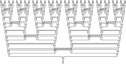


2
Much better. However "generalize" and "aesthetic" are not objective. All questions must have an objective winning criterion. If you want to apply those characteristics, use popularity-contest. If you want shortest code, use code-golf. If you want to make a combination of the two, use code-challenge, but specify a formula. For example 1.25votes - 0.25length as this question does: http://codegolf.stackexchange.com/questions/23581/eiffel-tower-in-3d/23585#23585
– Level River St – 2014-03-25T00:30:53.303ok made those chgs you ask for. thx for feedback. – vzn – 2014-03-25T01:00:26.363
Oghh, I guess compiled VHDL or Verilog after all its optimizations should give the shortest answer. I'll try it later. – Kirill Kulakov – 2014-03-25T06:26:49.263
1A better winning criteria would be [tag:gate-golf] – TheDoctor – 2014-03-25T14:17:25.513
@TheDoctor ??? what is
gate-golf? that tag is nonexistent. note to participants: please state what language/visualization tool you are using. if anyone else wants to enter plz comment. otherwise will accept winner tonite. thx much to respondents so far this went "BTE" better than expected! – vzn – 2014-03-25T14:49:06.180@vzn If there are to be more such challenges, I think
gate-golfwould be a great tag to use. You should just be able to add the new tag to questions, then I think a moderator would have to approve/deny the new tag – Digital Trauma – 2014-03-25T16:37:23.537This would probably be better split into two challenges: 1. the "gate-golf" part and 2. the visualization part. They are quite distinct problems and I don't see any particular value added by having them clubbed into the same challenge. – Digital Trauma – 2014-03-25T16:39:31.817
DT maybe so for this site. the visualization makes it easier for voters to judge entrants, they can do so not nec on code alone. also it was intended as part of a larger project that involves easily visualizing circuit DAGs for more sophisticated analysis & other challenges that build on this one. re new challenges
– vzn – 2014-03-25T16:51:10.847Hmm wondering if I can use this: http://stackoverflow.com/questions/4085914/binary-divisibility-by-3. Probably not :)
– CompuChip – 2014-03-25T17:39:47.010CC are you joking? yeah that post is marked as dup of another with solutions similar to some below. nice find!
– vzn – 2014-03-25T18:03:30.660