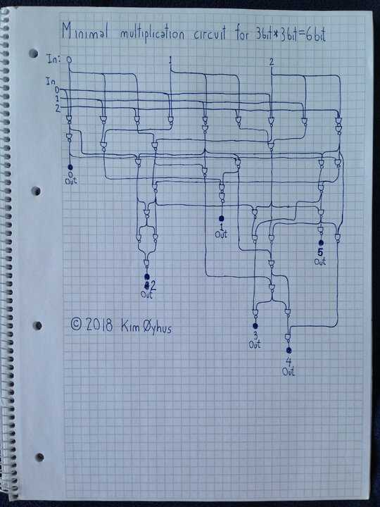
Build a multiplying machine using NAND logic gates

20

8

Based on my previous question of the same type, Build an adding machine using NAND logic gates, this time you're being asked to multiply instead of add.

Build a diagram of (two-wire) NAND logic gates that will take the input wires A1, A2, A4, B1, B2, B4, representing two binary numbers A to B from 0 to 7, and return values on the output wires C1, C2, C4, C8, C16, and C32, representing C, which is the product of A and B.

Your score is determined by the number of NAND gates you use (1 point per gate). To simplify things, you may use AND, OR, NOT, and XOR gates in your diagram, with the following corresponding scores:

  • NOT: 1
  • AND: 2
  • OR: 3
  • XOR: 4

Each of these scores corresponds to the number of NAND gates that it takes to construct the corresponding gate.

Lowest score wins.

Joe Z.

Posted 2013-08-08T05:39:59.863

Reputation: 30 589

Just to explain the bump: Someone posted here as an answer a claim that he has a 39-gate solution available. He didn't post the solution, but I'm still curious if 39 gates is actually possible. – John Dvorak – 2016-05-17T07:54:29.997

I'm trying to make a last-place example in Logisim. This stuff is hard. – Joe Z. – 2013-08-08T06:22:08.217

I got enough of this stuff in my school, no thanks. – Johannes Kuhn – 2013-08-08T08:02:56.777

7I have a universal optimizer for tasks like this. It provably finds the shortest program to compute a k-output boolean function. If I gave it a week, it could tell me if the 13 gate 2x2 multiplier it found is optimal. 3x3? I'll be dead before it finishes. – boothby – 2013-08-09T04:14:58.557

1That 13 gate 2x2 multiplier is optimal (and contained in Jan's answer). With that, and another few pieces I can optimize, I very strongly suspect 60 to be optimal for this problem. I really hope somebody proves me wrong. – boothby – 2013-08-10T05:49:34.250

@boothby Not really. Naive application of adder trees leads to an 18-gate solution (4 ANDs, 2 half-adders), which leads me to an idea: I should be able to steal^k^k^k^k^k utilise the 13-gate 2x2 multiplier. – John Dvorak – 2013-08-10T06:14:08.940

can I get a clock input, please? Maybe a shift-accumulate approach would lead to a smaller solution – John Dvorak – 2013-08-10T06:24:57.847

@boothby it turns out I can utilise a 13-gate 2x2 multiplier – John Dvorak – 2013-08-10T08:12:34.647

Looks like I mistraced some lines in your original, and it looked like a 2x2 only took 13. It's funny how just knowing the number of operations to shoot for makes it possible to find. I just installed the latest lingeling, and I think I can now optimize the 3x2. – boothby – 2013-08-10T14:39:00.157

Answers

24

60 55 50 48 gates

48-gate multiplier


The original (60 gates) was the systematic approach - multiply each digit with each, and then sum them together. Namely, see Wallace trees and Dadda trees

60-gate multiplier

The top half is the multiplication network - multiply each digit with each, and group output digits with the same weight. Some bits have been left inverted to save gates.

The second half is the adder network. Each box represents a single adder - either a half-adder (5 gates - 1x XOR and an inverter), or a full adder (9 gates - 2x XOR and NAND the inverted carry bits). The top are inputs, the bottom output is the sum, the left output is the carry-out. see the previous challenge

The 2x2 multiplier has then been hand-optimised to a custom-built 13-gate network, which is the optimal size as found by @boothby. Thanks!

Pasting it into the low-bit corner and reoptimising the adder tree saves five gates (see revision #2). Pasting it into the high-bit corner as well, however, produces overlap. A little bit of math tells us, however, that dropping the low-bit of the high multiplier solves the overlap and what's left to do is to add the remaining two bits and sum up stuff.

This alone, unfortunately, does not provide any savings, but it does open two optimisations. First, the two multipliers have two gates in common, and can be fused together. At this point, we're back at 55. Second, in the addition network, we don't need a half-adder because we know its carry will be zero. We can replace it with an OR. An OR is a NAND with its inputs inverted. This produces us with two 2-chains of NOTs on each branch, which can then be removed, for a total saving of five gates. Unfortunately, the half-adder at C16 still carries, so we cannot do the same there. Third, a full adder has a useful property: if you invert its inputs and its outputs, it still behaves the same. Since all its inputs are already inverted, we can just as well move the inverters behind it. Twice. We could have done the same in the original, but... oh well. We still have a half-adder with two inverted inputs. I want optimise this part more, but I doubt I can.

Since we're pulling out a NOT from inside a component, we have to signify that somehow. We have obtained a half-adder with inverted carry (AKA tapped XOR) at a cost of four gates.

In the meantime, we have also redrawn the diagram significantly.

John Dvorak

Posted 2013-08-08T05:39:59.863

Reputation: 9 048

The only part which looks potentially optimisable is the middle block of adders. The logical requirement is for a superfull-adder (takes 4 input bits, has two carry output bits) and a full adder; your implementation with two full-adders and two half-adders looks hard to improve. – Peter Taylor – 2013-08-08T09:32:44.593

I tried to make this exact network last night, but I'm not well-versed enough in logical networks, it seems. – Joe Z. – 2013-08-08T13:51:31.603

Most excellent! – boothby – 2013-08-10T14:26:07.063

9

39 gates

I am quite sure there are no simpler designs than mine here. It was very difficult to make. I make other minimal circuits too.

Transmission delay is indicated by downward position of each NAND gate on the sheet.

Minimal 3 bit multiplier

Verilog code and testing:

// MINIMAL 3 BIT MULTIPLICATOR
//
// The simplest 3 bit multiplicator possible, using 39 NAND gates only.
//
// I have also made multiplicators that are faster, more efficient,
// use different gates, and multiply bigger numbers. And I also do
// hard optimization of other circuits. You may contact me at
// kim.oyhus@gmail.com
// 
// This is my entry to win this hard Programming Puzzle & Code Golf
// at Stack Exchange:
// https://codegolf.stackexchange.com/questions/12261/build-a-multiplying-machine-using-nand-logic-gates/
//
// By Kim Øyhus 2018 (c) into (CC BY-SA 3.0)
// This work is licensed under the Creative Commons Attribution 3.0
// Unported License. To view a copy of this license, visit
// https://creativecommons.org/licenses/by-sa/3.0/


module mul3x3 ( in_000, in_001, in_002, in_003, in_004, in_005, out000, out001, out002, out003, out004, out005 );
  input  in_000, in_001, in_002, in_003, in_004, in_005;
  output out000, out001, out002, out003, out004, out005;
  wire   wir000, wir001, wir002, wir003, wir004, wir005, wir006, wir007, wir008, wir009, wir010, wir011, wir012, wir013, wir014, wir015, wir016, wir017, wir018, wir019, wir020, wir021, wir022, wir023, wir024, wir025, wir026, wir027, wir028, wir029, wir030, wir031, wir032;

  nand gate000 ( wir000, in_000, in_005 );
  nand gate001 ( wir001, in_000, in_004 );
  nand gate002 ( wir002, in_000, in_003 );
  nand gate003 ( out000, wir002, wir002 );
  nand gate004 ( wir003, in_004, in_001 );
  nand gate005 ( wir004, wir003, wir003 );
  nand gate006 ( wir005, in_003, in_002 );
  nand gate007 ( wir006, wir000, wir005 );
  nand gate008 ( wir007, in_004, in_002 );
  nand gate009 ( wir008, in_001, in_005 );
  nand gate010 ( wir009, wir008, wir007 );
  nand gate011 ( wir010, in_001, in_003 );
  nand gate012 ( wir011, wir001, wir010 );
  nand gate013 ( wir012, out000, wir004 );
  nand gate014 ( wir013, wir004, wir012 );
  nand gate015 ( wir014, wir011, wir012 );
  nand gate016 ( out001, wir014, wir014 );
  nand gate017 ( wir015, in_002, in_005 );
  nand gate018 ( wir016, wir015, wir015 );
  nand gate019 ( wir017, out000, wir016 );
  nand gate020 ( wir018, wir017, wir013 );
  nand gate021 ( wir019, wir016, wir018 );
  nand gate022 ( wir020, wir019, wir009 );
  nand gate023 ( wir021, wir020, wir017 );
  nand gate024 ( wir022, wir020, wir009 );
  nand gate025 ( wir023, wir022, wir021 );
  nand gate026 ( out005, wir022, wir022 );
  nand gate027 ( wir024, wir016, wir022 );
  nand gate028 ( wir025, wir006, wir018 );
  nand gate029 ( wir026, wir025, wir006 );
  nand gate030 ( wir027, wir025, wir018 );
  nand gate031 ( out002, wir026, wir027 );
  nand gate032 ( wir028, wir004, wir027 );
  nand gate033 ( wir029, wir023, wir028 );
  nand gate034 ( wir030, wir028, wir028 );
  nand gate035 ( wir031, wir030, wir021 );
  nand gate036 ( out004, wir031, wir024 );
  nand gate037 ( wir032, wir029, wir031 );
  nand gate038 ( out003, wir032, wir032 );
endmodule


module mul3x3_test; 
   reg  [5:0] AB; // C=A*B
   wire [5:0] C;

  mul3x3 U1 ( 
  .in_000 (AB[0]), 
  .in_001 (AB[1]), 
  .in_002 (AB[2]), 
  .in_003 (AB[3]), 
  .in_004 (AB[4]), 
  .in_005 (AB[5]), 
  .out000 (C[0]), 
  .out001 (C[1]), 
  .out002 (C[2]), 
  .out003 (C[3]), 
  .out004 (C[4]), 
  .out005 (C[5])
  ); 

  initial  AB=0;
  always  #10  AB = AB+1;
  initial  begin
    $display("\t\ttime,\tA,\tB,\tC"); 
    $monitor("%d,\t%b\t%b\t%b",$time, AB[5:3], AB[2:0],C); 
  end 
  initial  #630  $finish; 
endmodule


// iverilog -o mul3x3_test mul3x3_test.v
// vvp mul3x3_test

Kim Øyhus

KimOyhus

Posted 2013-08-08T05:39:59.863

Reputation: 351

2Do you have a proof that your answer is valid? – Jonathan Frech – 2018-09-19T18:51:53.660

3

I would recommend diagramming this in Logisim (it's free), so that it can easily be seen and tested.

– mbomb007 – 2018-09-19T19:31:26.663

It is too big to be proved as minimal, except perhaps by a future quantum computer. So I use statistical methods to verify its optimality. It still takes an excessive amount of computing time. – KimOyhus – 2018-09-19T20:33:15.820

2Jonathon asked for a proof of validity, rather than a proof of optimality. I don't think you need to prove it valid. But it would be nice if it were easier for us to test whether this is valid, rather than taking your word for it – H.PWiz – 2018-09-20T17:21:08.203

4

This does work: try it online!

– Anders Kaseorg – 2018-09-23T06:13:23.503

It's not necessary, but it would be great to hear how you came up with this – trichoplax – 2018-09-24T05:10:29.160

If you're still intending to license this commercially, it's worth getting advice on whether the copyright declaration overrides Stack Exchange's default licensing of user contributions (see the link at the bottom of every page). It says CC-BY-SA 3.0, which explicitly gives everyone the right to use the content, "for any purpose, even commercially" – trichoplax – 2018-09-24T05:18:03.353

I should consider that, yes. But at the moment I am just too busy. And solutions to other puzzles coming along. I can change that copyright later if necessary. As for commercialisations, I have other designs for that, optimised for more realistic gates and needs. – KimOyhus – 2018-09-25T06:15:44.313