30
7
In a similar spirit as this question, your mission is to create the best-looking logo in at most 1K of code.
Rules:
At most 1K of code (inclusive), no external data.
The answer with the most upvotes wins.
Have fun!
30
7
In a similar spirit as this question, your mission is to create the best-looking logo in at most 1K of code.
Rules:
At most 1K of code (inclusive), no external data.
The answer with the most upvotes wins.
Have fun!
44
1kB? Luxury. I can even pretty-print the output rather than removing all unnecessary whitespace. (The indentation does, of course, use tabs, which Markdown converts to spaces, so that's why the char count might seem higher than the actual 977. Removing unnecessary whitespace drops it to 861).
The overlaps are handled correctly by drawing the rings in one direction, then applying a clip and drawing them in the other direction. The colours and ratios are extracted from an official document which for some reason uses Bézier curves rather than circles.
<?xml version="1.0" encoding="UTF-8" standalone="yes"?>
<svg xmlns="http://www.w3.org/2000/svg" xmlns:xlink="http://www.w3.org/1999/xlink" width="504" height="228">
    <defs>
        <clipPath id="t">
            <rect width="504" height="114" />
        </clipPath>
    </defs>
    <g fill="none" stroke-width="12">
        <g id="u" transform="translate(82,82)" stroke="#0b8ed8">
            <g id="O">
                <circle r="72" stroke="#fff" stroke-width="20" />
                <circle r="72" />
            </g>
        </g>
        <g id="y" transform="translate(167,146)" stroke="#f9a91f">
            <use xlink:href="#O" />
        </g>
        <g id="k" transform="translate(252,82)" stroke="#231f20">
            <use xlink:href="#O" />
        </g>
        <g id="g" transform="translate(337,146)" stroke="#009e59">
            <use xlink:href="#O" />
        </g>
        <g transform="translate(422,82)" stroke="#ee2049">
            <use xlink:href="#O" />
        </g>
        <g clip-path="url(#t)">
            <use xlink:href="#g" />
            <use xlink:href="#k" />
            <use xlink:href="#y" />
            <use xlink:href="#u" />
        </g>
    </g>
</svg>
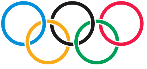
16PS If anyone wants to argue that SVG isn't a programming language (and I'd be very inclined to agree), consider this a PHP program in the style of many PHP submissions to this site which just echo literal text. – Peter Taylor – 2014-01-22T12:04:31.607
omg it looks amazing though. SVG is niceee – None – 2014-01-23T23:32:06.957
39
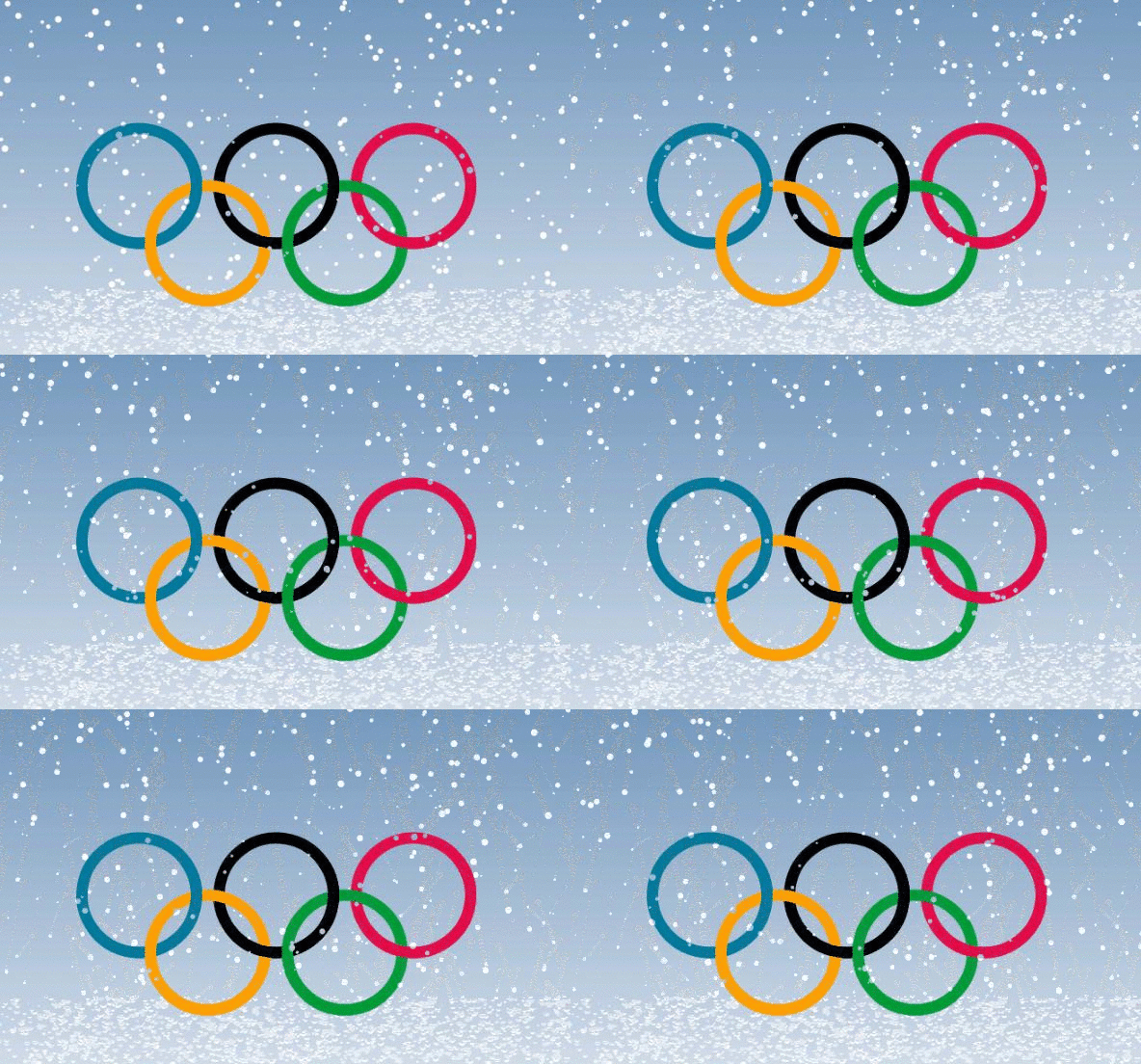
Playing with canvas.
Not sure if it is 1024 or 1000 the K is for, but managed to get it down to 1000 982 940 :D
Only suitable for WebKit browsers. Chrome OK. Firefox a mess. Might look into making it cross browser.
var w=window;w.onload=function(){function e(e,t){return r()*(t-e+1)+e}function d(e,t){function r(e,t,r,i){c.beginPath();c[u]="xor";c.strokeStyle="#"+e;c.arc(t,r,66,n*i[0],n*i[1]);c.stroke();c[u]="destination-atop";c.arc(t,r,66,n*i[1],n*i[0]);c.stroke()}var i=79+e,s=66+t,o=158,a=[2,1.2],f=[1.8,.8];c.lineWidth=13;r("007a9c",e,t,f);r("ffa100",i,s,a);r("000",e+=o,t,f);r("009b3a",i+=o,s,a);r("e10e49",e+=o,t,f)}var t=Math,n=t.PI,r=t.random,i,s,o=0,u="globalCompositeOperation",a=document.getElementById("c"),f=w.innerWidth,l=w.innerHeight,c=a.getContext("2d"),h=9,p=[];a.width=f;a.height=l;for(i=0;i<l;++i){p.push({x:r()*f,y:r()*l,r:e(1,3),d:e(1,l)})}setInterval(function(){c.clearRect(0,0,f,l-h);d(f/2-200,l-200);c[u]="xor";c.fillStyle="#fff";c.beginPath();o+=e(0,7)?.01:-.01;for(i=0;i<l-h;++i){s=p[i];c.moveTo(s.x,s.y);c.arc(s.x,s.y,s.r,0,n*2);s.y+=t.cos(o+s.d)+1+s.r/9;s.x+=(i%2?1:-1)*t.sin(o)*.4;if(s.x>f+7||s.x<-7||s.y>l-(h-1.2)){p[i]={x:r()*f,y:-9,r:s.r,d:s.d}}}c.fill();if(h<l/1.7)h+=l/9e3},32)}
940: Dropped wrapping it in onload and rely on script being inserted at end of body tag + alignment bug and Firefox fix.
function e(e,t){return r()*(t-e+1)+e}function d(e,t){function r(e,t,r,i){c.beginPath();c[u]="xor";c.strokeStyle="#"+e;c.arc(t,r,66,n*i[0],n*i[1]);c.stroke();c[u]="destination-over";c.arc(t,r,66,n*i[1],n*i[0]);c.stroke()}var i=79+e,s=66+t,o=158,a=[2,1.2],f=[1.8,.8];c.lineWidth=13;r("007a9c",e,t,f);r("ffa100",i,s,a);r("000",e+=o,t,f);r("009b3a",i+=o,s,a);r("e10e49",e+=o,t,f)}var w=window,t=Math,n=t.PI,r=t.random,i,s,o=0,u="globalCompositeOperation",a=document.getElementById("c"),f=w.innerWidth,l=w.innerHeight,c=a.getContext("2d"),h=9,p=[];a.width=f;a.height=l;for(i=0;i<l;++i,p.push({x:r()*f,y:r()*l,r:e(1,3),d:e(1,l)}));setInterval(function(){c.clearRect(0,0,f,l-h);d(f/2-158,l-200);c[u]="xor";c.fillStyle="#fff";c.beginPath();o+=e(0,7)?.01:-.01;for(i=0;i<l-h;++i){s=p[i];c.moveTo(s.x,s.y);c.arc(s.x+=(i%2?.4:-.4)*t.sin(o),s.y+=t.cos(o+s.d)+1+s.r/9,s.r,0,n*2);if(s.y>l-(h-1.2)){p[i].x=r()*f;p[i].y=-9}}c.fill();if(h<l/1.7)h+=l/9e3},32)
http://jsfiddle.net/Ifnak/XSBLg/embedded/result/
http://jsfiddle.net/Ifnak/4fSWm/5/embedded/result/
Loads in Firefox as well as Chrome, but is rather heavy on resources in FF. Using requestAnimationFrame() helped a bit, but not enough.
Note that snow lays on bottom, thus scroll down to see the slow growth. Initially had some overpainting on the ground, but could not make it fit into 1024 chr.
2Nice! It also works in IE11. – Danko Durbić – 2014-01-28T14:55:36.177
Works absolutely fine on Firefox 27.0.1. – Nathan Osman – 2014-02-25T00:46:44.320
32
From my answer in the Mathematica.SE Q&A:
ring[x_, y_, v_, t_] :=
  Table[
    {1.2 y, -v x, 0} + {Cos@i, Sin@i}.{{0, -1, 0}, {1, 0, 1/4 - v/2}},
    {i, 0, 2 π, π/200}
  ] ~Tube~ t

Graphics3D[
  Riffle[
    {Cyan, Yellow, Darker @ Gray, Green, Red},
    Array[ring[Sqrt@3/2, #, # ~Mod~ 2, 0.17] &, 5, 0] ],
  Boxed -> False,
  ViewPoint -> {0, 0, ∞}
]
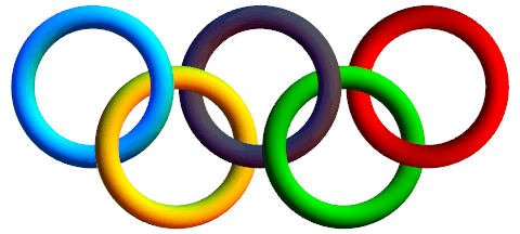
Edit: In version 10 the default lighting style changed; to render the graphic above one will need to add the Option Lighting -> "Classic" to Graphics3D.
Further playing with lighting to produce a flat two-dimensional affect:
Graphics3D[
  Riffle[
    Glow /@ {Hue[.59], Hue[.13], Black, Hue[.3, 1, .7], Hue[0, 1, .85]},
    Array[ring[Sqrt@3/2, #, # ~Mod~ 2, 0.13] &, 5, 0] ],
  Boxed -> False,
  ViewPoint -> {0, 0, ∞},
  Lighting -> None
]
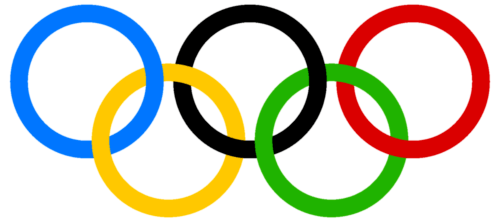
For Oliver who said my first result was "too 3D-ish" here is an actual 2D rendering via jVincent's code with my refactoring, also from the linked thread:
ringSegment[mid_, deg_, color_] := {CapForm["Butt"],
  Thickness[0.042], White,                   Circle[mid, 1, deg],
  Thickness[0.03],  RGBColor @@ (color/255), Circle[mid, 1, deg + {-0.1, 0.1}]}

blue   = {  0, 129, 188};
yellow = {255, 177,  49};
black  = { 35,  34,  35};
green  = {  0, 157,  87};
red    = {238,  50,  78};

Graphics @ GraphicsComplex[
  {{2.5, 0}, {1.3, -1}, {0, 0}, {5, 0}, {3.8, -1}},
  ringSegment @@@
   {{1, {0, 5/4 π},      black},
    {2, {0, π},          yellow},
    {3, {0, 2 π},        blue},
    {2, {-π 9/8, 1/4 π}, yellow},
    {4, {0, 5/4 π},      red},
    {5, {0, 7/8 π},      green},
    {1, {5/4 π, 5/2 π},  black},
    {5, {7/8 π, 2 π},    green},
    {4, {-3/4 π, 1/4 π}, red}}
 ]
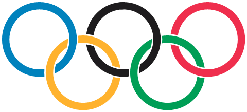
@Oliver Updated just for you. – Mr.Wizard – 2015-01-02T01:13:42.230
Wow! Can you tell me where you can download Mathmatica? – Oliver Ni – 2015-01-02T02:15:37.870
@Oliver It is commercial product, and rather expensive even for individual, noncommerical use, but if you are still interested you can get a 15-day trial version from: http://www.wolfram.com/mathematica/trial/
– Mr.Wizard – 2015-01-02T02:18:37.6401@Oliver you can now get a free version of Mathematica if you have a raspberry pi – trichoplax – 2015-06-26T12:05:46.987
@trichoplax Now Open Cloud lets one freely run modest programs in a browser interface: https://develop.open.wolframcloud.com/app/view/newNotebook
– Mr.Wizard – 2017-03-11T12:55:38.73028
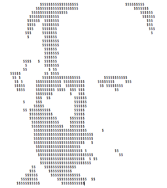
Sadly, a certain head of state seems to be the headline subject of most Olympic news so far. Thus, here is my freestyle logo (mascot?) for the 2014 Games.
w=?$;"UW[NASY_LAQVgKAPSlKAOKGLnHAOIHMnHAOHILpHANHJLqFAOFLKAVMAVMAWKAWLAWKAMIHFGK
NFMLAMGOFFGAGJPGFIAHGFFOWPPAIGFFKQFOKMJHAIJJQGNLGFMAJIJNFIGHFHSGASMMFHHASHGGPK
MFJHTKARJSKAMGFOPJAPPOJAPRKLAQRJLAQTHLAR^LFARaARaAR]HFASZAS[FFRGAT_QGAUZGFFG
U]AQGITAPHKPANKKSALMNSGGAJPOP".codepoints{|r|r-=69;$><<(r<0??\n:(w=w==?$?' ':?$)*r)}
Output: (Back up and squint. Sorry for the primitive rendering but he deserves no better.)
6$$$, sad but true :D – ybeltukov – 2014-01-22T05:22:17.300
25
convert \
  -size 330x150 xc:white -strokewidth 10 -fill none \
  -stroke \#0885c2 -draw 'arc 100,100 10,10 0,360' \
  -stroke black -draw 'arc 210,100 120,10 0,360' \
  -stroke \#ed334e -draw 'arc 320,100 230,10 0,360' \
  -stroke \#fbb132 -draw 'arc 155,140 65,50 0,360' \
  -stroke \#1c8b3c -draw 'arc 265,140 175,50 0,360' \
  -stroke \#0885c2 -draw 'arc 100,100 10,10 -20,10' \
  -stroke black -draw 'arc 210,100 120,10 -20,10' -draw 'arc 210,100 120,10 90,120' \
  -stroke \#ed334e -draw 'arc 320,100 230,10 90,120' \
  x:
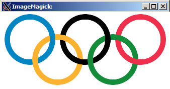
Sample output:
23
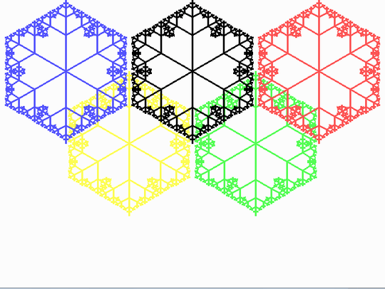
Winter Olympics? How about some fractal snowflakes instead of regular rings.
The recursion for the centre branch is pretty obvious: (dx,dy)= 0.5(dx,dy). Left and right branches are based on rotation by matrix multiplication:
x= x cos(a) - y sin(a)
y= x sin(a) + y cos(a)
1/4 = 0.5 cos(60) and 7/16 is a good approximation of 0.5 sin(60).
uses graph;
var gd, gm : integer;
var n:integer;

Procedure tree(x,y,dx,dy: integer);
begin
  if dx*dx+dy*dy>0 then begin
    line(x, y, x+dx, y+dy);
    tree(x+dx, y+dy, dx div 2, dy div 2);
    tree(x+dx, y+dy, dx div 4 + dy*7 div 16, dy div 4 - dx*7 div 16);
    tree(x+dx, y+dy, dx div 4 - dy*7 div 16, dy div 4 + dx*7 div 16);
  end;
end;

begin
  gd := D4bit;
  gm := m640x480;
  initgraph(gd,gm,'');
  setbkcolor(white); clearviewport;
  setbkcolor(black); setlinestyle(0,0,3);

  For n:=-1 to 1  do  begin
    setColor(yellow);
    tree(215,240-120*n,0,120*n);
    setColor(lightgreen);
    tree(425,240-120*n,0,120*n);
    setColor(black);
    tree(320,120-120*n,0,120*n);
    setColor(lightred);
    tree(530,120-120*n,0,120*n);
    setColor(lightblue);
    tree(110,120-120*n,0,120*n);
  end;
  readln;
  closegraph;
end.
. .
Nice. If you can add a good amount of randomness to the algorithm, you may reuse it in Let's simulate a random snowflake.
– manatwork – 2014-01-31T11:23:18.26016
Similar to my SVG answer, but
Note that I've not tried to golf it, despite the possibility of some interesting tricks (like -57*~dir instead of 57*(1+dir). It's at 923 chars, but golfs down to 624 quite easily.
import java.awt.*;
import java.awt.image.BufferedImage;
import java.io.File;
import javax.imageio.ImageIO;

public class Rings {
    public static void main(String[] args) throws Exception {
        int[] pal = new int[] {0x0b8ed8, 0xf9a91f, 0x231f20, 0x009e59, 0xee2049};
        BufferedImage img = new BufferedImage(505, 229, BufferedImage.TYPE_INT_ARGB);
        Graphics2D g = img.createGraphics();
        g.setRenderingHint(RenderingHints.KEY_ANTIALIASING, RenderingHints.VALUE_ANTIALIAS_ON);
        for (int dir = -1; dir < 2; dir += 2) {
            g.setClip(0, 57 * (1 + dir), 520, 114);
            for (int ring = 2 - 2 * dir; ring != 2 + 3 * dir; ring += dir) {
                for (int subring = 0; subring < 2; subring++) {
                    g.setColor(new Color(pal[ring] | (subring - 1)));
                    g.setStroke(new BasicStroke(20 - 8 * subring));
                    g.drawOval(10 + 85 * ring, 10 + 64 * (ring & 1), 144, 144);
                }
            }
        }
        ImageIO.write(img, "PNG", new File("rings.png"));
    }
}
16
Again, a C64 answer, but this time I'm allowed to use sprites! Yay!
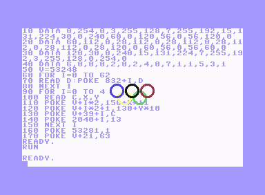
I remember if you wanted to use sprites, you'd begin your program with a lots of boring DATA statements. To define a "high resolution" (24x21 pixels) monochromatic sprite pattern you need 63 bytes. There's actually an online sprite editor that calculates the DATA for you, so:
10 DATA 0,254,0,3,255,128,7,255,192,15,131,224,30,0,240,60,0,120,56,0,56,120,0
20 DATA 60,112,0,28,112,0,28,112,0,28,112,0,28,112,0,28,120,0,60,56,0,56,60,0
30 DATA 120,30,0,240,15,131,224,7,255,192,3,255,128,0,254,0
I'll also need some more DATA for the colours and positions. I just copied that from my answer to the original Olympic Games Logo question:
40 DATA 6,0,0,0,2,0,2,4,0,7,1,1,5,3,1
Then, you'd usually set V=53248. This 53248 must be an important number, because I still remember it 25 years later :) It turns out it is the base address of VIC-II (Video Interface Controller):
50 V=53248
Then I read the sprite pattern into the memory starting at the address 832. It feels weird to just write to a memory location, no allocating, no new, nothing like that :) The start address needs to be a multiple of 64.
60 FOR I=0 TO 62
70 READ D:POKE 832+I,D
80 NEXT I
I'll be using the same pattern for all the sprites.
90 FOR I=0 TO 4
100 READ C,X,Y
C is the colour code, X and Y are horizontal and vertical positions of the circles.
A few more POKEs are needed:
110 POKE V+I*2,150+X*11
120 POKE V+I*2+1,130+Y*10
V+0, V+2, V+4, etc... are the horizontal locations of each sprite, while V+1, V+3, V+5... are vertical. The sprite colours start at the register V+39:
130 POKE V+39+I,C
The sprite data pointers start at 2040, and since the data starts at 832, we get 832/64=13, so:
140 POKE 2040+I,13
150 NEXT I
To turn on the sprites I set bits 0-4 of the register V+21. I also changed the background to white, so we can see the blue circle.
160 POKE 53281,1
170 POKE V+21,31
That's it!
Great! Don't know if I remember correctly, but maybe you can double (in hardware) the x/y size of the sprites. I'm sure you could do this on a C128. – Gabriele D'Antona – 2014-01-23T07:53:09.130
Yup, you can set bits of V+23 for double height, and V+29 for double width. (bit #x for sprite #x). – Danko Durbić – 2014-01-23T08:30:27.170
11
Size: 876 bytes (12 lines, line with 72 characters and end of line)
\documentclass{standalone}\usepackage{tikz}\def\W{3.762bp}\def\R{71.682
bp}\def\D{12.9041bp}\usetikzlibrary{calc,hobby}\def\Y{-71.7013bp}\def\X
{169.5538bp}\begin{document}\tikz[use Hobby shortcut,every path/.style=
{line width=\W,double distance=\D, white}]{\def\Z{coordinate}\path(0,0)
\Z(A)++(\X,0)\Z(C)++(\X,0)\Z(E)($(A)!.5!(C)$)++(0,\Y)\Z(B)++(\X,0)\Z(D)
;\def~#1#2{\definecolor{#1}{cmyk}{#2}} ~A{1,.25,0,0}~B{0,.342,.91,0}~C{
0,0,0,1}~D{1,0,.91,.06}~E{0,.94,.65,0}\def~#1#2#3#4{\draw[save Hobby p%
ath={#1},double=#1,overlay](#1)+([closed] 225:\R)..+([#2]315:\R)..+([#3
]45:\R)..+([#4]135:\R); \path let\n!={\R+\D/2}in(#1)+(-\n!,0)+(\n!,0)+(
0,-\n!)+(0,\n!);}\def\0#1{\draw[double=#1,restore and use Hobby path={%
#1}{disjoint,invert soft blanks}];}~A{}{blank=soft}{}~B{}{}{blank=soft}
~C{}{blank=soft}{}\0B\0A~E{blank=soft}{}{}~D{}{}{}\0C\0E}\end{document}
Size: 817 bytes in one line and with two optimizations:
tikz of class standalone, see comment of Wheat Wizard.soft=blank can be shortened by defining a style b.\documentclass[tikz]{standalone}\def\W{3.762bp}\def\R{71.682bp}\def\D{12.9041bp}\usetikzlibrary{calc,hobby}\def\Y{-71.7013bp}\def\X{169.5538bp}\begin{document}\tikz[use Hobby shortcut,every path/.style={line width=\W,double distance=\D,white},b/.style={blank=soft}]{\def\Z{coordinate}\path(0,0)\Z(A)++(\X,0)\Z(C)++(\X,0)\Z(E)($(A)!.5!(C)$)++(0,\Y)\Z(B)++(\X,0)\Z(D);\def~#1#2{\definecolor{#1}{cmyk}{#2}} ~A{1,.25,0,0}~B{0,.342,.91,0}~C{0,0,0,1}~D{1,0,.91,.06}~E{0,.94,.65,0}\def~#1#2#3#4{\draw[save Hobby path={#1},double=#1,overlay](#1)+([closed]225:\R)..+([#2]315:\R)..+([#3]45:\R)..+([#4]135:\R); \path let\n!={\R+\D/2}in(#1)+(-\n!,0)+(\n!,0)+(0,-\n!)+(0,\n!);}\def\0#1{\draw[double=#1,restore and use Hobby path={#1}{disjoint,invert soft blanks}];}~A{}b{}~B{}{}b~C{}b{}\0B\0A~E b{}{}~D{}{}{}\0C\0E}\end{document}
The following longer version is probably easier to understand.
The overlapping of the rings is handled by drawing the rings with blank segments first. Then at a later stage, the rings are drawn again, but this time the blank segments are filled and the other already drawn segments of the rings remain untouched. Therefore clipping is not used at all.
The ring with the white margins is drawn by circle with a double line. The area between the lines is filled with the color of the ring and the thinner double lines form the outer and inner white margin.
The colors and dimensions are taken from the PDF page description of page 5 of the official document (see the answer of Peter Tayler).
\nofiles % .aux file is not needed
\documentclass[tikz]{standalone}
\usetikzlibrary{calc}
\usetikzlibrary{hobby}

\newcommand*{\xshift}{169.5538bp}
\newcommand*{\yshift}{-71.7013bp}
\newcommand*{\radius}{71.6821bp}
\newcommand*{\whitelinewidth}{3.762bp}
\newcommand*{\colorlinewidth}{12.9041bp}

\definecolor{color@A}{cmyk}{1, .25, 0, 0}
\definecolor{color@B}{cmyk}{0, .342, .91, 0}
\definecolor{color@C}{cmyk}{0, 0, 0, 1}
\definecolor{color@D}{cmyk}{1, 0, .91, .06}
\definecolor{color@E}{cmyk}{0, .94, .65, 0}

\begin{document}
  \begin{tikzpicture}[
    use Hobby shortcut,
    every path/.style = {
      line width      = \whitelinewidth,
      double distance = \colorlinewidth,
      white,
    },
  ]
    % define center coordinates for the five rings
    \path
      (0,0) coordinate (center@A)
      ++(\xshift, 0) coordinate (center@C)
      ++(\xshift, 0) coordinate (center@E)
      ($(center@A)!.5!(center@C)$) ++(0, \yshift) coordinate (center@B)
      ++(\xshift, 0) coordinate (center@D)
    ;
    % \drawring draws the first part of the ring with blank parts
    \newcommand*{\drawring}[4]{%
      \draw[
        save Hobby path = {path@#1},
        double          = {color@#1},
        overlay,
      ]
        (center@#1)
        +([closed] 225:\radius) .. +([#2] 315:\radius) ..
        +([#3] 45:\radius) .. +([#4] 135:\radius)
      ;
    }
    % \finishring draws the blank parts of the rings
    \newcommand*{\finishring}[1]{%
      \draw[
        double                     = {color@#1},
        restore and use Hobby path = {path@#1}{
          disjoint,
          invert soft blanks
        },
      ];
    }
    \drawring{A}{}{blank=soft}{}
    \drawring{B}{}{}{blank=soft}
    \drawring{C}{}{blank=soft}{}
    \finishring{B}
    \finishring{A}
    \drawring{E}{blank=soft}{}{}
    \drawring{D}{}{}{}
    \finishring{C}
    \finishring{E}
    % set calculated bounding box
    \useasboundingbox
      let \n{r} = {\radius + \colorlinewidth/2}
      in
        (center@A) +(-\n{r}, \n{r}) % upper left corner
        (center@B -| center@E) +(\n{r}, -\n{r}) % lower right corner
    ;
  \end{tikzpicture}
\end{document}
To save a couple of bytes you can use \documentclass[tikz]{standalone} thanks to this tip.
@WheatWizard Thanks, answer is updated and further shortened by defining style b to avoid the lengthy blank=soft that is used four times. – Heiko Oberdiek – 2017-04-18T21:15:36.273
10
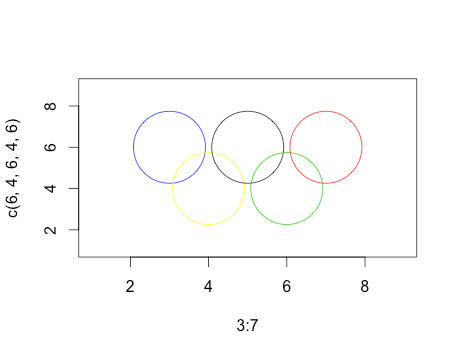
Using CRAN-R statistics.
l=c(1,9);plot(3:7,c(6,4,6,4,6),col=c(4,7,1,3,2),cex=10,ylim=l,xlim=l)
10
C++ 1024 bytes
Updated: Now with antialiasing. Code has been somewhat de-golfed while still fitting in (exactly) 1K.
Doesn't use any library functions except ostream functions to write output file.
#include <fstream>

namespace {
typedef double d;

int w=512;
d a=1./6,g=1./w,h=1./72,j=h+g,k=h-g,r=5./36;

struct p{d x,y;}ps[]={{5*a,a},{4*a,2*a},{3*a,a},{2*a,2*a},{a,a}};
struct c{unsigned char r,g,b;}cs[]={{237,51,78},{28,139,60},{0,0,0},{251,177,50},{8,133,194}};

d abs(d x) {return x<0?-x:x;}

d sqrt(d x) {
    d e=1e-6,y=1;
    for(;abs(y*y-x)>e;y=.5*(y+x/y));
    return y;
}

d dist(p c,p z) {
    d u=z.x-c.x,v=z.y-c.y;
    return abs(r-sqrt(u*u+v*v));
}

c lerp(c a,c b,d t) {
    auto l=[=](d a,d b){return a+(b-a)*t;};
    return {l(a.r,b.r),l(a.g,b.g),l(a.b,b.b)};
}

d smoothstep(d z) {
    z=(z-j)/(k-j);
    z=z<0?0:z>1?1:z;
    return z*z*(3-2*z);
}

c color(p z) {
    c o{255,255,255};
    for(int i=0,j;i<5;++i){
        j=z.y<.25?i:4-i;
        o=lerp(o,cs[j],smoothstep(dist(ps[j],z)));
    }
    return o;
}
}

int main() {
    std::ofstream o("r.ppm",std::ofstream::binary);
    o<<"P6 "<<w<<" "<<w/2<<" 255\n";
    for(int y=0;y<w/2;++y)
        for(int x=0;x<w;++x)
            o.write((char*)&color(p{x*g,y*g}),3);;
}
Outputs a .ppm file:
+1 for not even including <cmath> – epidemian – 2015-01-02T03:14:10.947
1This isn't [tag:code-golf]: you can feel free to make your code legible, provide it fits in 1kB. – Peter Taylor – 2014-01-22T22:43:00.933
9
I feel like I'm a little late to the party, but maybe I can make up for that with the first GLSL submission on this site. It is meant to be used as the fragment shader for a screen-filling primitive, and expects the viewport resolution in the iResolution uniform.
Colors and positions are "borrowed" from Peter Taylor's submission. I had to shorten some variable names to get below 1024 characters, but I hope it's still readable.
See it at Shadertoy (if your browser supports WebGL).
uniform vec3 iResolution;

float circle(vec2 pos, float r) {
    return clamp(r - distance(gl_FragCoord.xy, pos), 0., 1.);
}

float ring(vec2 pos, float r, float d) {
    return circle(pos, r + d) * (1. - circle(pos, r - d));
}

void paint(vec3 color, float a) {
    gl_FragColor.rgb = mix(gl_FragColor.rgb, color, a);
}

void main() {
    struct r_t {
        vec2 pos;
        vec3 col;
    } rs[5];
    rs[0] = r_t(vec2( 82, 146), vec3(.04, .56, .85));
    rs[1] = r_t(vec2(167,  82), vec3(.98, .66, .12));
    rs[2] = r_t(vec2(252, 146), vec3(.14, .12, .13));
    rs[3] = r_t(vec2(337,  82), vec3(.00, .62, .35));
    rs[4] = r_t(vec2(422, 146), vec3(.93, .13, .29));

    float s = min(iResolution.x / 504., iResolution.y / 228.);
    vec2 b = (iResolution.xy - vec2(504, 228) * s) * .5;
    bool rev = gl_FragCoord.y > iResolution.y * .5;

    gl_FragColor.rgb = vec3(1);

    for (int i = 0; i < 5; ++i) {
        r_t r = rev ? rs[4 - i] : rs[i];
        paint(vec3(1), ring(r.pos * s + b, 72. * s, 11. * s));
        paint(r.col,   ring(r.pos * s + b, 72. * s,  6. * s));
    }
}
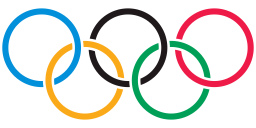
5
I've replaced my original answer with one that draws on regions and their intersections. The code size is 973 bytes, ungolfed.
Regions 1-5 are the rings. The rings have an inner radius of 2.5 units; the outer radius is 3 units. The ratio of inner to outer ratio, and the general logic of the approach are to be found here.
i = Implicit Region;
R1 = i[6.25 <= (x + 6.4)^2 + y^2 <= 9 , {x, y}];
R2 = i[6.25 <= x^2 + y^2 <= 9 , {x, y}];
R3 = i[6.25 <= (x - 6.4)^2 + y^2 <= 9 , {x, y}];
R4 = i[6.25 <= (x + 3.2)^2 + (y + 3)^2 <= 9 , {x, y}];
R5 = i[6.25 <= (x - 3.2)^2 + (y + 3)^2 <= 9 , {x, y}];
If we plot these rings straightaway, they do not interlock. Notice that the yellow ring lies atop the blue and black rings; the green ring lies atop both the black and red rings.
Show[{RegionPlot[R1, PlotStyle -> Blue, BoundaryStyle -> Blue],
  RegionPlot[R2, PlotStyle -> Black, BoundaryStyle -> Black],
  RegionPlot[R3, PlotStyle -> Red, BoundaryStyle -> Red],
  RegionPlot[R4, PlotStyle -> Yellow, BoundaryStyle -> Yellow],
  RegionPlot[R5, PlotStyle -> Green, BoundaryStyle -> Green]
  }, PlotRange -> All, PerformanceGoal -> "Quality",
 ImageSize -> Large, AspectRatio -> 1/2,
 Frame -> False]
Regions 6, 8, 10 and 12 are rectangles that serve to specify which intersection of two rings to focus on.
Regions 7, 9, 11, and 13 are the "ring overlaps" where the ring on the bottom should be on top.
R6 = Rectangle[{-5, -1}, {-2, 1}];
R7 = RegionIntersection[R1, R4, R6];
R8 = Rectangle[{2, -1}, {4, 1}];
R9 = RegionIntersection[R2, R5, R8];
R10 = Rectangle[{-2, -3}, {2, -2}];
R11 = RegionIntersection[R2, R4, R10];
R12 = Rectangle[{5, -3}, {7, -2}];
R13 = RegionIntersection[R3, R5, R12];

Show[{RegionPlot[R1, PlotStyle -> Blue, BoundaryStyle -> Blue],
  RegionPlot[R2, PlotStyle -> Black, BoundaryStyle -> Black],
  RegionPlot[R3, PlotStyle -> Red, BoundaryStyle -> Red],
  RegionPlot[R4, PlotStyle -> Yellow, BoundaryStyle -> Yellow],
  RegionPlot[R5, PlotStyle -> Green, BoundaryStyle -> Green],
  RegionPlot[R7, PlotStyle -> Blue, BoundaryStyle -> Blue],
  RegionPlot[R9, PlotStyle -> Black, BoundaryStyle -> Black],
  RegionPlot[R11, PlotStyle -> Black, BoundaryStyle -> Black],
  RegionPlot[R13, PlotStyle -> Red, BoundaryStyle -> Red]},
PlotRange -> All, PerformanceGoal -> "Quality",
 ImageSize -> Large, AspectRatio -> 1/2,
 Frame -> False]
The following highlights the intersection regions where colours were "flipped".
This was accomplished by changing the BoundaryStyle of regions 7, 9, 11, and 13 to White.
1@friol, I improved the intersections by using regions. – DavidC – 2015-09-06T00:29:19.093
1It took a year and a half, but you've finally found how to make pretty intersections :D – Beta Decay – 2015-09-06T08:35:22.693
Yesterday I saw some Olympic rings and realised that I could use regions to solve the intersection issue. The prior ones were too ugly to leave as they were. – DavidC – 2015-09-06T11:08:05.930
4Can't you do something aesthetically better in 1k? those intersections are ugly! – Gabriele D'Antona – 2014-01-23T07:50:08.197
3
Given an html element, this function will create the rings as 3D objects and then render a still image to the element. Works in browsers that support WebGL. FIDDLE
function Logo(l){
    var s, c, r;
    s = new THREE.Scene();
    c = new THREE.PerspectiveCamera(45, 4/3, 1, 500);
    c.position.set(75,0,300);
    c.lookAt(new THREE.Vector3(0,0,0));
    var rings = [
        new THREE.Mesh(ring(), mat(0x0885c2)),
        new THREE.Mesh(ring(), mat(0xfbb132)),
        new THREE.Mesh(ring(), mat(0x000000)),
        new THREE.Mesh(ring(), mat(0x1c8b3c)),
        new THREE.Mesh(ring(), mat(0xed334e))
    ];
    for(var i = 0; i < rings.length; i++){
        s.add(rings[i]);
        rings[i].position.set(i*55-125,-(i%2)*50,0);
        rings[i].rotation.set(0,(i%2*2-1)*.18,0,'xyz');
    }
    r = new THREE.WebGLRenderer();
    r.setSize(400, 300);
    l.appendChild(r.domElement);
    r.render(s, c);
}
function ring(){ return new THREE.TorusGeometry(50, 8, 16, 32); }
function mat(color){ return new THREE.MeshBasicMaterial({color: color}); }
2
Not small by any stretch of the imagination, but kept as terse-yet-readable as possible and still under 1k.
#include <SFML/Graphics.hpp>

using namespace sf;

int main() {
    CircleShape circles[5];
    Color backcolor(255,255,255);
    Color colors[5] = {
        Color(0x0b,0x8e,0xd8),
        Color(0xf9,0xa9,0x1f),
        Color(0x23,0x1f,0x20),
        Color(0x00,0x9e,0x59),
        Color(0xee,0x20,0x49),
    };

    for (int i = 0; i < 5; i++) {
        circles[i] = CircleShape(144, 60);
        circles[i].setPosition(15+160*i, 46+160*(i&1));
        circles[i].setFillColor(Color::Transparent);
        circles[i].setOutlineColor(colors[i]);
        circles[i].setOutlineThickness(-16);
    }

    RenderWindow window(VideoMode(960, 540), L"Olympic Logo", Style::Close);

    while (window.isOpen()) {
        Event event;

        while (window.pollEvent(event))
            if (event.type == Event::Closed)
                window.close();

        window.clear(backcolor);

        for (int i = 0; i < 5; i++)
            window.draw(circles[i]);

        window.display();
    }

    return 0;
}
Edit: Updated colors based on @Peter Taylor's SVG submission.
2
It was so short that the website refused to upload it until I added this description. The logo represents Olympic Games.
$ $ $
 $ $
1
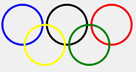
  Canvas.Pen.Width := 10;
  Canvas.Brush.Style:=bsClear;//To prevent solid background
  Canvas.Pen.Color:=clBlue; Canvas.Ellipse(20,30,220,230);
  Canvas.Pen.Color:=clBlack; Canvas.Ellipse(240,30,440,230);
  Canvas.Pen.Color:=clRed; Canvas.Ellipse(460,30,660,230);
  Canvas.Pen.Color:=clYellow; Canvas.Ellipse(130,130,330,330);
  Canvas.Pen.Color:=clGreen; Canvas.Ellipse(350,130,550,330);
0
made a solution based on a Java Swing GUI UltraGolfed edition (696 charas)
import java.awt.Color;import java.awt.Graphics;import javax.swing.JFrame;import javax.swing.JPanel;class A extends JFrame{public A(){JPanel j=new JPanel(){protected void paintComponent(Graphics g){;((java.awt.Graphics2D)g).setStroke(new java.awt.BasicStroke(3));g.setColor(new Color(0xb,0x8e,0xd8));g.drawOval(10, 10, 80, 80);g.setColor(new Color(0xf9,0xa9,0x1f));g.drawOval(50,40,80,80);g.setColor(new Color(0x23,0x1f,0x20));g.drawOval(90, 10, 80, 80);g.setColor(new Color(0,0x9e,0x59));g.drawOval(130,40,80,80);g.setColor(new Color(0xee,0x20,0x49));g.drawOval(170, 10, 80, 80);}};j.setBounds(0,0,600,400);setSize(600,400);add(j);}public static void main(String[]a){new A().setVisible(true);}}
Semiuncompressed one: (971)
import java.awt.Color;
import java.awt.Graphics;
import javax.swing.JFrame;
import javax.swing.JPanel;
class A extends JFrame
{
    public A()
    {
        JPanel j = new JPanel(){
        protected void paintComponent(Graphics g)
        {;
            ((java.awt.Graphics2D)g).setStroke(new  java.awt.BasicStroke(3));
            g.setColor(new Color(0xb,0x8e,0xd8));
            g.drawOval(10, 10, 80, 80);
            g.setColor(new Color(0xf9,0xa9,0x1f));
            g.drawOval(50,40,80,80);
            g.setColor(new Color(0x23,0x1f,0x20));
            g.drawOval(90, 10, 80, 80);
            g.setColor(new Color(0,0x9e,0x59));
            g.drawOval(130,40,80,80);
            g.setColor(new Color(0xee,0x20,0x49));
            g.drawOval(170, 10, 80, 80);}};
        j.setBounds(0,0,600,400);
        setSize(600,400);
        add(j);
    }
    public static void main(String[]a)
    {
        new A().setVisible(true);
    }
}
Could you add a screenshot? – Paŭlo Ebermann – 2015-09-09T20:08:23.160
0
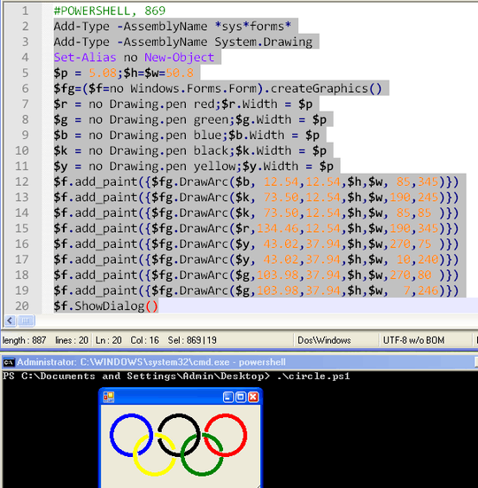
POWERSHELL , 869
code and output in screenshot
0
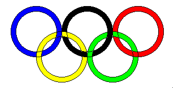
Each ring is made up of an inner/outer circle, then flood-filled.
Had to find the intersections manually and fill those individually (so you can still see some of the lines between them).
1 INK 0: PAPER 15: CLS: LET r=50
2 FOR x=1 TO 3
3 CIRCLE x*100,100,r: CIRCLE x*100,100,r-10
4 IF x<3 THEN CIRCLE (x*100)+50,150,r: CIRCLE (x*100)+50,150,r-10
5 NEXT x
6 INK 0: FILL 165,130: FILL 195,145: FILL 200,55: FILL 215,145: FILL 245,105
7 INK 9: FILL 100,55: FILL 130,130: FILL 145,105
8 INK 10: FILL 270,135: FILL 295,145: FILL 300,55
9 INK 12: FILL 205,145: FILL 215,120: FILL 250,195: FILL 255,105: FILL 280,120
10 INK 14: FILL 105,145: FILL 110,125: FILL 150,195: FILL 155,105: FILL 190,130
6Well, he did state directly "in a similar spirit as this question", so he practically said "hey, I know this is a duplicate" :D – Mike Koch – 2014-01-22T01:31:34.213
5Different winning criteria. So it is a similar question, but is not a duplicate. – Victor Stafusa – 2014-01-22T01:47:07.543
3
I'm actually glad someone else created a [tag:popularity-contest] version of my question with less criteria, as I was torn on which way to go when I wrote it.
– Adam Maras – 2014-01-22T03:02:40.503@AdamMaras Glad to hear that :) – chubakueno – 2014-01-22T03:21:55.273
I started a reopen discussion on Meta, as this question shouldn't have been close-voted.
– Adam Maras – 2014-01-22T15:10:52.363not a duplicate – DA. – 2014-01-22T16:58:58.380
Here's one using LaTeX/TikZ. (Posting as a comment because I didn't create it!) – ESultanik – 2014-01-23T17:41:25.033