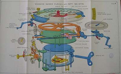
Vickers range clock
The Vickers Range Clock was a clockwork device used by the Royal Navy for continuously calculating the range to an enemy ship.

Overview
In 1903, Percy Scott described a device he'd invented which was similar to the Vickers clock.
In April 1904, Vickers worked with Scott and patented their device, samples of which were available for trials in 1905. In 1906, the Royal Navy ordered 246 units for use on their ships. More than one might be installed, to allow for tracking multiple targets.[1]
The device consisted of a circular dial with a single central rotating pointer, like a clock. The dial was engraved with the ranges in yards. The clockwork motor drove the pointer at a constant rate determined by a control on the right hand side of the device. This had a handle and its own dial, on which the rate of change of range (or "range rate") could be selected. This was calculated by other means, often by use of a Dumaresq or a time-and-range plot. A second rotating handle was fitted to the left of the clock. This was connected by gears to the dial plate, which rather than being fixed as on a clock, could be rotated. One turn of the handle would rotate the scale 100 yd (91 m) relative to the pointer. Thus the clock could be set to the initial range to a ship, or corrections could be made to update the reading without disturbing the mechanism.[2]
The range on the dial was the range as passed to gunners for firing, and as such included any corrections necessitated by time of flight, wind, etc., rather than being a true instantaneous record of distance to the enemy. By 1913, a second red pointer had been added to the original black one, attached to it by a friction grip, which could be adjusted relative to the original hand, so that one indicated true range and the other the corrected range for targeting.[3]
Once some shots had been fired, spotters would report the fall of shell (which could be observed because of the large waterspouts where the shells hit the sea) and the range would be corrected up or down depending whether the shells were short or over the enemy. Initial estimates of range were obtained using optical rangefinders.
The dial was fitted with three separate scales reading 2,000–6,000 yd (1,800–5,500 m), 6,000–10,000 yd (5,500–9,100 m) and 10,000–14,000 yd (9,100–12,800 m) in 100-yard steps, with marked subdivisions every 25 yd (23 m). The handle for adjusting the dial was added from 1908; previously, the initial position of the dial plate had to be set by rotating it directly. Initial models had the rate setting dial calibrated in both knots and 'seconds per 50 yards'. This was altered in 1909 to yards per minute, which standardised measurement was used on other equipment designed to work with the clock.[4]
An important aspect of the Vickers range clock, as well as other designs using a wheel-on-disc drive for the variable speed motor, such as the electrical clock used in the Dreyer Fire Control Table, was that it could only generate ranges according to a constant range rate. In most firing scenarios, the range rate would change continuously. In such cases, the operators of the clock would periodically alter the range rate in discrete increments as conditions suggested.
Mechanism
Variable speed was obtained using a rotating metal disc driving a rubber wheel resting against it. The position of the wheel could be moved in and out along a radius of the disc, so that the wheel turned at different speeds (faster the further out). Operating errors would occur from adjusting the wheel, as the wheel tended to slide as it was dragged across the face of the spinning disc as it was adjusted. The workaround adopted was to adjust the rate quickly and in a discrete manner, accepting that the generated ranges would deviate moderately from the desired continuous hyperbolic curves that predominated in use. In 1909, alterations were made to the clockwork drive to improve reliability of the governed speed and to increase the power of the drive.[5]
A small aperture on the dial would reveal a visual tell-tale which indicate that the clock's spring required winding.
Notes
- Brooks p. 43
- Brooks pp. 25–27
- Brooks p. 53
- Brooks pp. 53–54
- Brooks pp. 54–55
References
- Brooks, John (2005). Dreadnought Gunnery at the Battle of Jutland: The Question of Fire Control. London: Frank Cass Publishers. ISBN 0-7146-5702-6.
- B.R. 1534 Handbook on Minor Fire Control Instruments, 1946 as transcribed at maritime.org