Schilling rudder
A Schilling rudder is a specific type of profiled rudder used on certain boats and ships.

Concept
The Schilling profile is designed to improve the effective lift generated by the rudder and hence improve the maneuverability of the craft, especially at slow speeds. The rudder is effective in both forward and reverse. It has been claimed that a Schilling rudder "combines the highest lateral forces with the best course stability.[1]
Use
Like all rudders, the main effect of a Schilling rudder is to deflect the flow of water generated by the propeller. Schilling rudders are most commonly used on ships that are difficult to maneuver, particularly large ships such as container ships and oil tankers, slow-moving ships and boats, longer and narrower ships, or boats with slow-moving propellers.[2]
Additionally, a twin-rudder configuration and/or a bow thruster can significantly contribute to the maneuverability of even the largest ships. When the rudders are at angles of 90 degrees or more to the direction of the propeller generated thrust, they can direct the thrust forward and provide a significant braking effect on the ship.
Shape
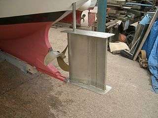
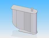
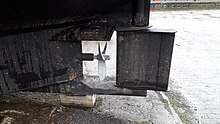
There is little reliable information available in the public domain regarding the exact shape of the Schilling rudder. However, the basic shape is a relatively simple ‘fish shape’ if viewed from above (as seen in the figure to the right). Also, pair of flat plates are typically fitted top and bottom to prevent or minimize end-effect on the aerofoil.


The basic principle proportions of a typical Schilling rudder layout are as follows:
- Rounded leading edge
- Maximum width of aerofoil at 20% chord.
- Taper to 60% chord.
- Flat to 80% chord
- Flare to 100%
Or in other words, a bulbous widening for 1/5 of the total length of the rudder blade, with a streamlined narrowing for 2/5 of the length leading to a flat section lasting for around 1/5 of a cord-length, finalizing in a blunt-ended flared trailing edge for the remaining fifth.
The width of the trailing edge should be 33% of the maximum width of the profiles. The width of the end plates to be around twice the maximum width of the rudder.
The height should be similar to the diameter of the propeller, with the chord length being up to 1.2 × propeller diameter. If extreme maneuverability is not required, chord length can be reduced to a minimum of 0.55 × propeller diameter.
Around 40% balance should be provided, aka, rudder in front of the rudder pivot.
The distance from the trailing edge of the propeller to the leading of the rudder should be a minimum of 0.2 × propeller diameter, and the maximum effective angle of operation for a single rudder is 2*70 degrees.
No information as to the layout or profile design of a twin rudder system is contained within this article.
Other names
Rudders of the same or similar profile are also referred to as the MacLear-Thistle or Mystic rudder.
Alternatives
Alternatives to the Shilling rudder concept include conventional aerofoil shapes, i.e. without the flared end, flap rudders, Kort nozzles and azimuth thrusters.
See also
- Azimuth thruster – Steerable propulsion pod under a watercraft
- Ducted propeller – Marine propeller with a non-rotating nozzle
- Kitchen rudder – Type of directional propulsion system for vessels
- Flap rudder – Marine rudder with a trailing edge flap
- Pleuger rudder – A thruster assisted ship's rudder
References
- "Becker Schilling Rudder". Retrieved 4 April 2019.
- Nagarajan, Vishwanath; Kang, Dong Hoon; Hasegawa, Kazuhiko; Nabeshima, Kenjiro (2008-02-01). "Comparison of the mariner Schilling rudder and the mariner rudder for VLCCs in strong winds". Journal of Marine Science and Technology. 13 (1): 24–39. doi:10.1007/s00773-007-0245-x. ISSN 1437-8213.