Royer oscillator
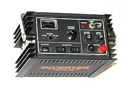
A Royer oscillator is an electronic relaxation oscillator that employs a saturable-core transformer. It was invented and patented in 1954 by George H. Royer.[1] It has the advantages of simplicity, low component count, rectangle waveforms, and easy transformer isolation. By making maximum use of the transformer core, it also minimises the size and weight of the transformer. The classic Royer circuit outputs square waves. There is another converter design often described as a "resonant Royer" which generates sinewaves. This was, apparently, first described in 1959 by Baxandall and therefore should be called the "Baxandall converter". Its differences are explained below. Both versions are widely used, mainly as power inverters.
Circuit description


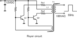
The Royer circuit consists of a saturable-core transformer with a center-tapped primary winding, a feedback winding and (optionally) a secondary winding. The two halves of the primary are driven by two transistors in push-pull configuration. The feedback winding couples a small amount of the transformer flux back in to the transistor bases to provide positive feedback, generating oscillation. The oscillation frequency is determined by the maximum magnetic flux density, the power supply voltage, and the inductance of the primary winding.
The basic Royer generates square wave output.[2]
The need to use a saturable-core limits the choice of core material. Some common materials are:
| Core material | Saturation Flux Density / G | Core Losses W/cm3 at 50 kHz |
|---|---|---|
| Toshiba MB | 6000 | 0.49 |
| Metglas2714A | 6000 | 0.62 |
| Square Permalloy 80 (0.5 mil) | 7800 | 0.98 |
| Square Permalloy 80 (1 mil) | 7800 | 4.2 |
| Ferrite Type 84 | 4000 | 4 |
Current mode operation
A drawback of the voltage mode operation is that the stress on switch transistors is high during the cross over time, when both the voltage and current are high. This drawback is alleviated by using current mode operation. This is achieved by inserting an inductor in the transformer center tap supply. This inductor drops the center tap voltage down when the dI/dt would be very high in voltage mode. This improved version is called current-fed Royer oscillator in some books.[3]
Applications (and sine-wave variants)
The classic Royer oscillator circuit (with or without current drive) is used in some DC–AC inverters where square wave output is acceptable for the load. It was also heavily used in the 1970s in switching power supplies (by rectifying the output) and typically implemented with bipolar transistors.[4] This circuit relies solely on transformer core saturation to cause switching between the two states.

Sinewave variant
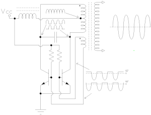
There are three major differences between the Royer converter and Baxandall's resonant design, though the literature is mixed [5][6]. Firstly, the sinewave circuit adds a capacitor in parallel with the centre tapped transformer primary, which forms a resonant LC ("tank") circuit. Secondly, an inductor is connected in series with the supply voltage to the transformer primary tap. These components change the nature of the circuit completely from the Royer design.
When one transistor is on, its collector voltage is near zero, limited by the saturation voltage. It operates with a constant current, set by the inductor. The current in the primary of the transformer splits into two parts, each side conducting half a sinewave but in anti-phase, and each with an average, or d.c. offset, of half the supply voltage. The opposing currents always balance but the whole primary "sees" the complete sinewave. In this manner, a sinewave is able to be generated while allowing the transistors to switch alternately fully on and off in push-pull mode. This is the only resemblance to the Royer converter.
The centre tap voltage swings up and down as the inductor opposes current change. As a result the waveform appears much like a full-wave rectifier. The d.c. supply voltage equates to the average, so the tap peaks at approximately (pi/2)*Vcc. As the transformer acts like a 2:1 autotransformer on the primary, the "off" transistor collector voltage reaches double, or pi times Vcc.
Finally the third major difference is that the transformer does not, or should not, saturate. Switching between the two transistors is brought about simply through the resonating primary changing polarity every half cycle.
A circuit of this type was used for example in driving the CRT of the Tektronix 547 oscilloscope.[7] A circuit employing a similar idea appears in a 1973 patent assigned to Bell Telephone Laboratories[8] and as mentioned, in a 1959 conference paper by P.J. Baxandall,[9]who provided a clear description of its operation.
The Baxandall converter has been used recently in driving fluorescent tubes from low voltage sources, often using rechargeable batteries, for emergency lighting and camping etc. Also in his 1959 paper, Baxandall described a voltage-switched variant of the sinewave oscillator. This variant seems to have been the forerunner of most two-transistor drivers for compact fluorescent lamps (CFL's) and which has been extended recently to drive low voltage LED lamps too.
Another application of the Baxandall converter is in powering CCFLs. CCFLs exhibit a degradation in their current-to-light output efficiency in the presence of harmonics, so the resonant circuit is the one used to drive them.[10] In order to provide light intensity adjustment, an integrated circuit typically drives a pulse-width modulated signal in the gate of an additional transistor, forming a step-down converter with the feeding choke.[11] Other integrated circuits control also the two oscillator transistors and sense the zero valley of the transformer mid tap to do this.[12]
References
- Royer oscillator circuit United States Patent 2783384
- Pressman et al., p. 266
- Pressman et al., p. 271
- Mike Golio (2010). The RF and Microwave Handbook. CRC Press. p. "3–66". ISBN 978-1-4200-3676-3.
- http://datasheets.maximintegrated.com/en/ds/MAX1739-MAX1839.pdf
- EDN letter exchange "A Royer by any other name" between Bryce Hesterman and Jim Williams. Published on November 21, 1996.
- Jim Williams (1998). The Art and Science of Analog Circuit Design. Newnes. p. 145. ISBN 978-0-08-049943-7.
- United States Patent 3818314 Fig. 3
- P.J. Baxandall, "Transistor Sine-Wave LC Oscillators", International Convention on Transistors and Associated Semiconductor Devices, 25 May 1959, fig 5, p. 751
- Williams (1998), p. 157
- http://www.ti.com/lit/ds/symlink/ucc3973.pdf UCC3973 data sheet
- http://www.ti.com/lit/ds/symlink/uc3872.pdf UC3872 data sheet
Further reading
- Abraham Pressman; Keith Billings; Taylor Morey (2009). Switching Power Supply Design, 3rd Ed. McGraw Hill Professional. pp. 266–278. ISBN 978-0-07-159432-5. Has a detailed analysis of the FET version of the (classic) Royer oscillator.
- Johnson I. Agbinya, ed. (2012). Wireless Power Transfer. River Publishers. pp. 187–193. ISBN 978-87-92329-23-3. Contains an analytic derivation of the formulas for the resonant Royer circuit and a comparison with data measured from an actual circuit (using MOSFETs).
- Royer, G. H. (1955). "A switching transistor D-C to A-C converter having an output frequency proportional to the D-C input voltage". Transactions of the American Institute of Electrical Engineers, Part I: Communication and Electronics. 74 (3): 322. doi:10.1109/TCE.1955.6372293.. A 1955 paper by Royer on his circuit.
- George Henry (2000), "LX1686 Direct Drive CCFL Inverter Design". Microsemi Application Note AN-13. Contains a critique of the resonant Royer as used in CCFL applications (and proposes another inverter design).