Ring oscillator
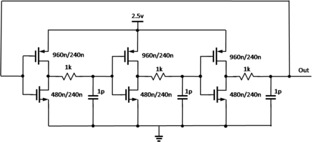
A ring oscillator is a device composed of an odd number of NOT gates in a ring, whose output oscillates between two voltage levels, representing true and false. The NOT gates, or inverters, are attached in a chain and the output of the last inverter is fed back into the first.

.svg.png)
Details
Because a single inverter computes the logical NOT of its input, it can be shown that the last output of a chain of an odd number of inverters is the logical NOT of the first input. The final output is asserted a finite amount of time after the first input is asserted and the feedback of the last output to the input causes oscillation.
A circular chain composed of an even number of inverters cannot be used as a ring oscillator. The last output in this case is the same as the input. However, this configuration of inverter feedback can be used as a storage element and it is the basic building block of static random access memory or SRAM.
The stages of the ring oscillator are often differential stages, that are more immune to external disturbances. This renders available also non-inverting stages. A ring oscillator can be made with a mix of inverting and non-inverting stages, provided the total number of inverting stages is odd. The oscillator period is in all cases equal to twice the sum of the individual delays of all stages.
A real ring oscillator only requires power to operate. Above a certain threshold voltage, oscillations begin spontaneously. To increase the frequency of oscillation, two methods are commonly used. Firstly, making the ring from a smaller number of inverters results in a higher frequency of oscillation, with about the same power consumption. Secondly, the applied voltage may be increased. In circuits where this method can be applied, it reduces the propagation delay through the chain of stages, increasing both the frequency of the oscillation and the current consumed. The maximum permissible voltage applied to the circuits limits the speed of a given oscillator.
Operation
To understand the operation of a ring oscillator, one must first understand gate delay. In a physical device, no gate can switch instantaneously. In a device fabricated with MOSFETs, for example, the gate capacitance must be charged before current can flow between the source and the drain. Thus, the output of every inverter in a ring oscillator changes a finite amount of time after the input has changed. From here, it can be easily seen that adding more inverters to the chain increases the total gate delay, reducing the frequency of oscillation.

The ring oscillator is a member of the class of time delay oscillators. A time-delay oscillator consists of an inverting amplifier with a delay element between the amplifier output and its input. The amplifier must have a gain greater than 1 at the intended oscillation frequency. Consider the initial case where the amplifier input and output voltages are momentarily balanced at a stable point. A small amount of noise can cause the amplifier output to rise slightly. After passing through the time-delay element, this small output voltage change will be presented to the amplifier input. The amplifier has a negative gain of greater than 1, so the output will change in the direction opposite to this input voltage. It will change by an amount larger than the input value, for a gain greater than 1. This amplified and reversed signal propagates from the output through the time-delay and back to the input where it is amplified and inverted again. The result of this sequential loop is a square-wave signal at the amplifier output with the period of each half of the square wave equal to the time delay. The square wave will grow until the amplifier output voltage reaches its limits, where it will stabilize. A more exact analysis will show that the wave that grows from the initial noise may not be square as it grows, but it will become square as the amplifier reaches its output limits.
The ring oscillator is a distributed version of the delay oscillator. The ring oscillator uses an odd number of inverters to give the effect of a single inverting amplifier with a gain of greater than one. Rather than having a single delay element, each inverter contributes to the delay of the signal around the ring of inverters, hence the name ring oscillator. Adding pairs of inverters to the ring increases the total delay and thereby decreases the oscillator frequency. Changing the supply voltage changes the delay through each inverter, with higher voltages typically decreasing the delay and increasing the oscillator frequency. Vratislav describes some methods of frequency-stability and power consumption improving of the CMOS ring-oscillator.[1]
If 't' represents the time-delay for a single Inverter and 'n' represents the number of Inverters in the Inverter chain, then the frequency of oscillation is given by
.[2]
Jitter
Period of ring oscillator vibrates in a random manner T=T+T' where T' is a random value. In high-quality circuits, the range of T' is relatively small compared to T. This variation in oscillator period is called jitter.[3] Local temperature effects cause the period of a ring oscillator to wander above and below the long-term average period.[4] When the local silicon is cold, the propagation delay is slightly shorter, causing the ring oscillator to run at a slightly higher frequency, which eventually raises the local temperature. When the local silicon is hot, the propagation delay is slightly longer, causing the ring oscillator to run at a slightly lower frequency, which eventually lowers the local temperature. So, the frequency of a silicon ring oscillator will generally be stable, when the ambient temperature is constant and factors of heat transfer from the device to the ambient environment do not vary. Note, however, that electronic materials other than silicon may not have the same positive relationship between temperature and propagation delay; if the relationship is negative, the frequency could be unstable (and thermal runaway is even a possibility, in theory).
Applications
- The voltage-controlled oscillator in most phase-locked loops is built from a ring oscillator.[5]
- Jitter of ring oscillators is commonly used in hardware random number generators.[3][4][6]
- A ring oscillator is sometimes used to demonstrate a new hardware technology, analogous to the way a hello world program is often used to demonstrate a new software technology.[7][8]
- Many wafers include a ring oscillator as part of the scribe line test structures. They are used during wafer testing to measure the effects of manufacturing process variations.[9]
- Ring oscillators can also be used to measure the effects of voltage and temperature on a chip.[10]
See also
Notes
| Wikimedia Commons has media related to Ring oscillators. |
- Vratislav MICHAL. "On the Low-power Design, Stability Improvement and Frequency Estimation of the CMOS Ring Oscillator". 2012
- Mandal, M.K. & Sarkar, B.C."Ring oscillators: Characteristics and applications"
- A Provably Secure True Random Number Generator with Built-in Tolerance to Active Attacks
- Andy Green. Whirlygig GPL Hardware RNG. 2010.
- Takahito MIYAZAKI Masanori HASHIMOTO Hidetoshi ONODERA. "A Performance Prediction of Clock Generation PLLs: A Ring Oscillator Based PLL and an LC Oscillator Based PLL"
- THE INTEL RANDOM NUMBER GENERATOR. CRYPTOGRAPHY RESEARCH, INC
- Slashdot Science: "IBM Creates Ring Oscillator on a Single Nanotube"
- Slashdot Hardware: "World's First Completely Transparent IC"
- "Ring oscillators for CMOS process tuning and variability control" by BHUSHAN Manjul; GATTIKER Anne; KETCHEN Mark B.; DAS Koushik K.
- "Analysis of a ring oscillator based on-chip thermal sensor" Archived 2014-03-28 at the Wayback Machine