Loading arm
A loading arm permits the transfer of liquid or liquefied gas from one tank to another through an articulated pipe system consisting of rigid piping and swivel joints to obtain flexibility.
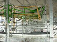
Transfer to or from a truck transported tank or rail transported tank requires a Top Loading Arm or a Bottom Loading Arm. Transfer to or from a ship or barge requires a marine loading arm.
Top and Bottom loading arm
- General feature of Top and Bottom loading arms

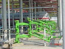
Both types of loading arms are typically made of 3 pipes – respectively called inner arm, outer arm and drop pipe. The size can be from 2” to 6”. These 3 pipes are connected by swivel joints. Swivel joints are required to provide the flexibility needed. The loading arm unfolds to get the required working envelope to load or unload the tanker, and the reverse is to retract or get a minimal space for parking or storage. Both types of loading arms may be mounted on a column or via a plate to an existing wall. Balancing is needed due to the weight of the steel piping. Balancing of the arm is made by counterweight or by a spring balance cylinder.
Top loading arm

Top loading arms are used to load or unload road or rail tankers. Loading or unloading is done through the manhole on the top of the tanker. Top loading arms can also be used for tight-fill, vapor recovery, marine and other applications when used with specially designed and engineered components, such as vapor plates, tapered hatch plugs, and inflatable hatch seals.[1] Depending on the nature of the product (not dangerous, without any toxic vapors...), the connection may be “open”, this means that the manhole is not sealed. A “Semi-Closed” connection can be made by a cone on the manhole of the tanker. A “Closed” connection is required for all dangerous and toxic products. This connection is made by a flange to the top of the tanker. A cone can be equipped with a vapour hose to prevent the vapors from being released to the atmosphere. Numerous accessories are available to make a loading arm more ergonomic and more effective: press down system, pneumatic up/down system, top level control, safety break valve, purge, drain...etc.
Bottom loading arm
This kind of arm is reserved for the unloading of road/rail tanker from the bottom, at the rear or side. The location of the connection has an influence on the length of the pipes. As an example, a rear connection requires a longer length of arms than for a side connection. The connection of this kind of loading arm can be made by flange, thread or by quick connection coupler such as a Dry Disconnect. There are also a numerous accessories which can be fitted to the Bottom loading arm to make it more ergonomic and more effective as described for the Top loading arm.
Marine loading arm
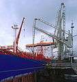
To load or unload a ship, a hose or loading arm is needed to follow the movement of the ship due to the dynamics of changing draft, changing tide, wind and other factors. A Marine Loading Arm offers a significant improvement over a hose in the transfer of liquids between vessel and shore because It provides an easier and more ergonomic operation, gives longer service life and permits Emergency Release Action without any spillage of product and without any pollution.
Like the Top and Bottom loading arm, the Marine Loading Arm is a system consisting of rigid piping and swivel joints to obtain flexibility. The OCIMF (Oil Companies International Marine Forum) and ASME have established guidelines for matters of strength calculations, working envelope and accessories. However the design of the loading arm is not included in this guideline and left to the individual manufacturer.
- Different design for Marine loading arm
The product line reposes on a fixed stand post or riser and is connected by an inner and an outer arm – both arms are movable parts. Balancing is needed due to the weight of the steel piping. Balancing of the Marine Loading Arm is done by a rotating counterweight, which is connected to the inner arm and the outer arm via a rigid pantograph. Small loading arms may be manually operated. The bigger ones are hydraulically operated.
The product line can be self supported or mounted on an independent support frame. Since the swivels are strong enough to absorb the weights of the product line, the liquid in the arms and the forces of the wind, the marine loading arm can be built as a self-supporting structure. Nowadays marine loading arms can also be built on an independent support frame as is required for LNG and highly corrosive liquids.
Recently the design of the marine loading arms has been significantly improved by the symmetric design. This new concept offers many advantages such as the equal distribution of forces on the swivel joints under all conditions, less force within the structure, reduces the weight of the loading arm, and permits larger working envelopes without requiring significantly stronger construction. Since the symmetric design has proven its effectiveness and its reliability. The symmetric design is also applicable to marine loading arms requiring an independent support frame.
 2 Marine loading arms connected to ship
 Marine loading arms connected to ship
 Marine loading arm with long outboard
 Marine loading arm connected to ship Air view
References
- "Top Loading Arms". OPW Engineered Systems. Retrieved 30 June 2020.
Further reading
- M.K.S. Sastry, Larry Haynes Seekumar, (2012) "Automation of Real Time Monitoring and Controlling of a Marine Loading Arm", Journal of Engineering, Design and Technology, Vol. 10 Iss: 2 Emerald Articleid: 17020853