Integral bridge
An integral bridge contains no expansion joints to accommodate enlargement due to increased temperature. Horizontal (axial) movements due to thermal expansion and braking loads are instead transferred to the fill adjacent to the abutment. The omission of the expansion joint removes a pathway for the penetration of chloride-bearing road salts to the bridge's sub-structure. In the United Kingdom there is a presumption that most new short to medium length bridges will be of the integral type.
An early example of an integral bridge is masonry arch bridge. Some of the earliest examples of integral bridges in reinforced concrete were constructed as part of the United Kingdom's M1 motorway in 1959.[1]
Description
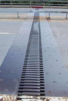
An integral bridge contains no expansion joints, spanning monolithically from abutment to abutment.[1] Movement due to thermal expansion and contraction or braking loads is accommodated by the end walls or abutments.[2][3] Where intermediate supports are specified (e.g. bridge piers) these may also serve to resist thermal expansion movements.[3]
The omission of the expansion joint removes a significant maintenance and durability issue, as it serves as a point of ingress for road salts which allows the abutment, piers and deck soffit concrete to come under chloride attack that can cause degradation and eventual span failure. A 1989 British study showed that the majority of expansion joints surveyed in existing bridges had failed and allowed water (and hence salt) ingress.[1]
The movement experienced at the abutment in an integral bridge is an order of magnitude greater than those designed with movement joints. The size of movement depends on the stiffness of the bridge structure and the fill adjacent to the abutment (which is subject to compaction). The movement is largest in the upper portion of the abutment, where thermal effects are greatest.[2] Highways England specify that integral bridges should be designed to limit movement to 20 millimetres (0.79 in).[3] Due to repeated expansion and contraction cycles the backfill adjacent to the abutment is subject to ratcheting, whereby the material's stiffness is increased. The maximum stiffness level is reached after around 100–200 thermal expansion cycles.[2]
Types
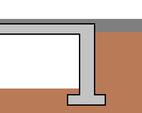
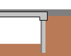
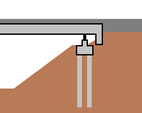
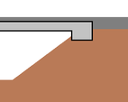
Highways England recognises four types of integral bridge, defined by the construction of their abutments:
- Frame abutments where the abutment acts as a retaining wall to the surrounding fill, connecting to the deck in a manner that allows for transfer of bending moments, shear forces and axial loads.[3]
- Embedded abutments, extending to a depth below the retained fill with restraint provided by the embedded length.[3]
- Bank pad abutments, designed to move horizontally to accommodate expansion and contraction of the deck. These must be of adequate weight (or a deck flexible enough) to avoid uplift forces due to differential settlement.[3]
- End screen abutments, which act only to retain the surrounding fill and transfer horizontal loads from the bridge deck to the fill. The vertical loads are transferred from the deck by means of a separate support system. The supports may be designed to take only vertical loading or accommodate the horizontal movement.[3]
Where bridge bearings are used on an integral bridge (as is often the case for end screen abutment types) the structure is sometimes referred to as semi-integral.[1]
Use
It is widely accepted that short to medium length bridges should be designed as integral structures to minimise maintenance requirements.[2] Highways England's Design Manual for Roads and Bridges (applicable to the whole of the UK and many parts of it, including the section on integral bridges, applying to the Republic of Ireland) states that all bridges with deck length less than 60 metres (200 ft) and skew of less than 30 degrees should be designed as integral structures unless there is a compelling reason to do otherwise.[1][3][4]
References
- "Integral bridges". The Concrete Society. Retrieved 12 February 2018.
- Rhodes, Steve. "Integral Bridges and the Modelling of Soil-Structure Interaction" (PDF). LUSAS. Retrieved 12 February 2018.
- "BA 42/96 Amendment no 1: The Design of Integral Bridges" (PDF). Design Manual for Roads and Bridges. Highways England. Retrieved 12 February 2018.
- "NRA addendum to BA 42/96 amendment no. 1 the design of integral bridges" (PDF). Transport Infrastructure Ireland. National Roads Authority. Retrieved 14 February 2018.
