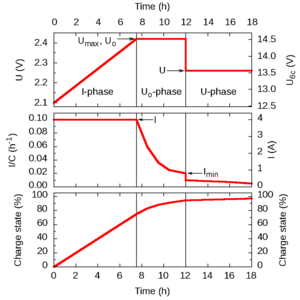
IUoU battery charging
IUoU is a DIN-designation[1] (DIN 41773) for a lead-acid battery charging procedure that is also known as 3-stage charging, 3-phase charging, or 3-step charging. It consists of three phases (or stages), to be executed by a battery charger. The three phases are: I-phase (constant electric current), Uo-phase (constant over-voltage), and U-phase (constant voltage). The purpose is to fully charge the battery in a relatively short time without reducing its life span and to indefinitely keep the battery charged as long as the charger is connected.

Stages
Stage 1 is called the I-phase, constant-current stage, or bulk charge stage. This phase occurs when an IUoU charger is connected to a deeply discharged battery. The charger provides a constant current, typically the maximum current that the charger is capable of producing. As a result of the current, the battery absorbs the charge and its voltage rises. The charger limits the maximum voltage to Umax, a constant or temperature-dependent maximum, typically around 2.4 V per cell. Once the Umax voltage is reached, typically when the battery is charged to 70–80% of its capacity,[1] the charger enters the Uo-phase. In case of a battery that is more than 80% full, this may happen immediately once the charger is switched on. Some chargers[1] may keep the voltage at Umax for some time and allow the current to drop to 80% of the constant-current value, before proceeding to the next stage.
Stage 2 is called the Uo-phase, constant-voltage boost stage, absorption stage, or topping charge. In this stage, the battery is continued being charged at a constant (over)voltage Uo, but the charge current is decreasing. The decrease is imposed by the battery. The voltage in the Uo-phase is too high to be applied indefinitely (hence, overvoltage), but it allows charging the battery fully in a relatively short time. The Uo-phase is concluded when the charge current goes below a threshold Imin, after which the U-phase is entered. This happens when the battery is charged to around 95% of its capacity.[1] Some chargers[2] follow this stage by a second constant-current stage (with a gradually increasing voltage) before continuing with the U-phase. The voltage Uo may be the same as Umax in the previous stage, or it may be taken slightly higher.
Stage 3 is called the U-phase or float charge state, the voltage is reduced to a value that is safe to be applied for long periods (weeks) without significantly reducing the lifetime of the battery. During this phase, the charge current decreases gradually to a small residual value that compensates for any self-discharge of the battery.
Voltages and currents
The current in the I-phase (stage 1) should be chosen depending on the capacity of the battery. In practice, it depends on the capability of the charger. The battery capacity C is expressed in Ah units, typically the C20 value based on a 20-hour discharge time.[3] The charging current (in A units) can be written as C/t where t is a time. For example, for a battery with C = 40 Ah, a current C/(10 h) (usually written as C/10, omitting the 'hours' as time unit) is equal to 4 A. The charging current is a compromise between charging time (favoring high currents), the prevention of damage due to overheating or gassing (favoring low currents), and cost of the charger (favoring low currents). Recommendations for the maximum charging current vary between C/10[2] and C/2.[3] At high charging currents, active cooling measures may be necessary to prevent overheating.[3]
The voltages in the U and Uo phases (stages 2 and 3) depend on the type of battery and the temperature. Batteries have varying numbers of cells (typically six for an automotive battery) and may be flooded-cell, absorbed-glass-matt (AGM), or gel-electrolyte types. The numbers in the table below are for a temperature around 20 °C (68 °F).[1][3] For temperatures that deviate more than about 5 °C (10 °F), a correction should be applied of −5 mV/°C (−2.8 mV/°F) per cell[1] or −0.03 V/°C (−17 mV/°F) for a 12 V (6-cell) battery (higher voltages at lower temperatures and vice versa).
| Battery type | Ref. | Stage 1 | Stage 2 | Stage 3 | ||
|---|---|---|---|---|---|---|
| Umax (V) | I | Uo (V) | Imin | U (V) | ||
| Wet/flooded, single cell | [1] | 2.32 | < C/5 | 2.42 | I/10 | 2.27 |
| [3] | 2.47 | < C/2 | 2.47–2.50 | C/100 | 2.25–2.30 | |
| [2] | 2.37–2.47 | C/10 | 2.37–2.47 | C/33 | 2.19 | |
| Wet/flooded, 6-cell (12 V) | [1] | 13.9 | < C/5 | 14.5 | I/10 | 13.6 |
| [3] | 14.8 | < C/2 | 14.8--15.0 | C/100
(Max 24 hours.[3]) |
13.5--13.8 | |
| AGM, 6-cell (12 V) | [1] | 13.9 | < C/5 | 14.5 | I/10 | 13.6 |
| [3] | 14.1 | < C/2 | 14.1--14.4 | C/100 | 13.6--13.8 | |
| Gel electrolyte, 6-cell (12 V) | [1] | 13.9 | < C/5 | 14.1 | I/10 | 13.6 |
| [3] | 14.1 | < C/2 | 14.1--14.4 | C/100 | 13.5--13.8 | |
| Deep-cycle antimony, 6-cell (12 V) | [3] | 14.7 | < C/2 | 14.7--14.9 | C/100 | 13.2--13.4 |
Special cases
A bad battery will have short I-phase and Uo-phase, but there is a risk of gassing, further damaging the battery.
If a battery is connected to a significant load during charging, the end of the Uo-phase may never be reached and the battery will gas and be damaged, depending on the charge current relative to the battery capacity.