Gurney equations
The Gurney equations are a set of mathematical formulas used in explosives engineering to relate how fast an explosive will accelerate an adjacent layer of metal or other material when the explosive detonates. This determines how fast fragments are released by military explosives, how quickly shaped charge explosives accelerate their liners inwards, and in other calculations such as explosive welding where explosives force two metal sheets together and bond them.[1]
The equations were first developed in the 1940s by Ronald Gurney[2] and have been expanded on and added to significantly since that time. The original paper by Gurney analyzed the situation of an exploding shell or bomb, a mass of explosives surrounded by a solid shell. Other researchers have extended similar methods of analysis to other geometries. All of the equations derived based on Gurney's methods are collectively called "Gurney equations".
Underlying physics
When an explosive adjacent to a layer of a metallic or other solid material detonates, the layer is accelerated both by the initial detonation shock wave and by the pressure of the detonation gas products. Gurney developed a simple and convenient formula based on the conservation laws of momentum and energy that model how energy was distributed between the metal shell and the detonation gases that is remarkably accurate in many cases.
A key simplifying assumption Gurney made was that there is a linear velocity gradient in the explosive detonation product gases, in situations were this is strongly violated, such as implosions, the accuracy of the equations break down. In the most common situations encountered in ordnance (shells surrounding explosives) this works remarkably well though. In such cases the approximations are within 10% of experimental or detailed numerical results over a wide range of metal mass (M) to explosive charge mass (C) ratios (0.1 < M/C < 10.0). This is due to offsetting errors in the simplified model. Ignoring rarefaction waves in the detonation gases causes the calculated velocity to be too high; the assumption of an initial constant gas density rather than the actual one of the gases being densest next the accelerated layer causes the value to be low, cancelling each other out. In consequence attempts to improve the accuracy of the Gurney model by making more realistic assumptions about one aspect or another may not actually improve the accuracy of the result.[3] [4] Cases where the Gurney approximations are not close are discussed in the section Anomalous predictions below.
Definitions and units
The Gurney equations relate the following quantities:
- C - The mass of the explosive charge
- M - The mass of the accelerated shell or sheet of material (usually metal). The shell or sheet is often referred to as the flyer, or flyer plate.
- V or Vm - Velocity of accelerated flyer after explosive detonation.
- N - The mass of a tamper shell or sheet on the other side of the explosive charge, if present.
- - The Gurney constant for a given explosive. This is expressed in units of velocity (millimeters per microsecond, for example) and compares the relative flyer velocity produced by different explosive materials.
For imploding systems, where a hollow explosive charge accelerates an inner mass towards the center, the calculations additionally take into account:
- Ro - Outside radius of the explosive charge.
- Ri - Inside radius of the explosive charge.
Gurney constant and detonation velocity
As a simple approximate equation, the physical value of is usually very close to 1/3 of the detonation velocity of the explosive material for standard explosives.[1] For a typical set of military explosives, the value of ranges from between 2.79 and 3.15.
| Density | Detonation velocity | ||
|---|---|---|---|
| Explosive | |||
| Composition B | 1.72 | 7.92 | 2.70 |
| Composition C-3 | 1.60 | 7.63 | 2.68 |
| Cyclotol 75/25 | 1.754 | 8.25 | 2.79 |
| HMX | 1.89 | 9.11 | 2.97 |
| LX-14 | 1.835 | 8.65 | 2.80 |
| Octol 75/25 | 1.81 | 8.48 | 2.80 |
| PBX 9404 | 1.84 | 8.80 | 2.90 |
| PBX 9502 | 1.885 | 7.67 | 2.377 |
| PETN | 1.76 | 8.26 | 2.93 |
| RDX | 1.77 | 8.70 | 2.83 |
| Tetryl | 1.62 | 7.57 | 2.50 |
| TNT | 1.63 | 6.86 | 2.44 |
| Tritonal | 1.72 | 6.70 | 2.32 |
Note that is dimensionally equal to kilometers per second, a more familiar unit for many applications.
The commonly quoted values for are what are called the terminal values, the limiting case of acceleration in the cylinder expansion tests used to measure it (at 19-26 mm expansion). There is also a prompt value that may be measured for smaller expansion radii (5-7 mm). When no clarification is given in the literature, it is normally the limiting value [5]
Fragmenting versus nonfragmenting outer shells
The Gurney equations give a result that assumes the flyer plate remains intact throughout its acceleration. For some configurations, this is true; explosive welding, for example, uses a thin sheet of explosive to evenly accelerate flat plates of metal and collide them, and the plates remain solid throughout. However, for many configurations where materials are accelerated outwards, the expanding shell fractures due to stretching. When it fractures, it usually breaks into many small fragments due to the combined effects of ongoing expansion of the shell and stress relief waves moving into the material from fracture points.[1]
For brittle metal shells, the fragment velocities are typically about 80% of the value predicted by the Gurney formulas.
Effective charge volume for small diameter charges
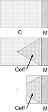
The basic Gurney equations for flat sheets assume that the sheet of material is large diameter.
Small explosive charges, where the explosive's diameter is not significantly larger than its thickness, have reduced effectiveness as gas and energy are lost to the sides.[1]
This loss is empirically modeled as reducing the effective explosive charge mass C to an effective value Ceff which is the volume of explosives contained within a 60° cone with its base on the explosives/flyer boundary.
Putting a cylindrical tamper around the explosive charge reduces that side loss effectively, as analyzed by Benham.
Anomalous predictions
In 1996, Hirsch described a performance region, for relatively small ratios of in which the Gurney equations misrepresent the actual physical behavior. [6]
The range of values for which the basic Gurney equations generated anomalous values is described by (for flat asymmetrical and open-faced sandwich configurations):
For an open-faced sandwich configuration (see below), this corresponds to values of of 0.5 or less. For a sandwich with tamper mass equal to explosive charge mass ( ) a flyer plate mass of 0.1 or less of the charge mass will be anomalous.
This error is due to the configuration exceeding one of the underlying simplifying assumptions used in the Gurney equations, that there is a linear velocity gradient in the explosive product gases. For values of outside the anomalous region, this is a good assumption. Hirsch demonstrated that as the total energy partition between the flyer plate and gases exceeds unity, the assumption breaks down, and the Gurney equations become less accurate as a result.
Complicating factors in the anomalous region include detailed gas behavior of the explosive products, including the reaction products' heat capacity ratio, γ.
Modern explosives engineering utilizes computational analysis methods which avoid this problem.
Equations
Cylindrical charge
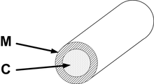
For the simplest case, a long hollow cylinder of metal is filled completely with explosives. The cylinder's walls are accelerated outwards as described by:[1]
This configuration is a first-order approximation for most military explosive devices, including artillery shells, bombs, and most missile warheads. These use mostly cylindrical explosive charges.
Spherical charge
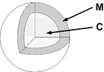
A spherical charge, initiated at its center, will accelerate a surrounding flyer shell as described by:[1]
This model approximates the behavior of military grenades, and some cluster bomb submunitions.
Symmetrical sandwich

A flat layer of explosive with two identical heavy flat flyer plates on each side will accelerate the plates as described by:[1]
Symmetrical sandwiches are used in some Reactive armor applications, on heavily armored vehicles such as main battle tanks. The inward-firing flyer will impact the vehicle main armor, causing damage if the armor is not thick enough, so these can only be used on heavier armored vehicles. Lighter vehicles use open-face sandwich reactive armor (see below). However, the dual moving plate method of operation of a symmetrical sandwich offers the best armor protection.
Asymmetrical sandwich

A flat layer of explosive with two flat flyer plates of different masses will accelerate the plates as described by:[1][7][8]
Let:
Infinitely tamped sandwich
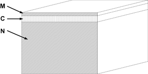
When a flat layer of explosive is placed on a practically infinitely thick supporting surface, and topped with a flyer plate of material, the flyer plate will be accelerated as described by:[1]
Open-faced sandwich
A single flat sheet of explosives with a flyer plate on one side, known as an "open-faced sandwich", is described by:[1]
Since:
then:
which gives:
Open-faced sandwich configurations are used in Explosion welding and some other metalforming operations.
It is also a configuration commonly used in reactive armour on lightly armored vehicles, with the open face down towards the vehicle's main armor plate. This minimizes the reactive armor units damage to the vehicle structure during firing.
Imploding cylinder
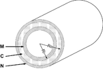
A hollow cylinder of explosive, initiated evenly around its surface, with an outer tamper and inner hollow shell which is then accelerated inwards ("imploded") rather than outwards is described by the following equations.[9]
Unlike other forms of the Gurney equation, implosion forms (cylindrical and spherical) must take into account the shape of the control volume of the detonating shell of explosives and the distribution of momentum and energy within the detonation product gases. For cylindrical implosions, the geometry involved is simplified to include the inner and outer radii of the explosive charge, Ri and Ro.
While the imploding cylinder equations are fundamentally similar to the general equation for asymmetrical sandwiches, the geometry involved (volume and area within the explosive's hollow shell, and expanding shell of detonation product gases pushing inwards and out) is more complicated, as the equations demonstrate.
The constant was experimentally and analytically determined to be 1.0.
Imploding spherical
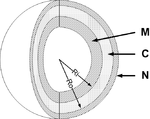
A special case is a hollow sphere of explosives, initiated evenly around its surface, with an outer tamper and inner hollow shell which is then accelerated inwards ("imploded") rather than outwards, is described by:[9]
The spherical Gurney equation has applications in early nuclear weapons design.
Applications
See also
- Explosives engineering
- Explosive velocity
- Table of explosive detonation velocities
References
- Cooper, Paul W. (1996). "Acceleration, Formation, and Flight of Fragments". Explosives Engineering. Wiley-VCH. pp. 385–394. ISBN 0-471-18636-8.
-
Gurney, R. W. (1943). "The Initial Velocities of Fragments from Bombs, Shells, and Grenades, BRL-405" (PDF). Ballistic Research Laboratory, Aberdeen, Maryland. Cite journal requires
|journal=(help) - Walters, William P. (1986). Explosive Loading of Metals and Related Topics, BRL-SP-56 (PDF). Ballistic Research Laboratory, Aberdeen, Maryland. p. VIII-1.
- Meyers, Marc A. (2007). Dynamic Behavior of Materials. John Wiley & Sons, Inc. p. 240. doi:10.1002/9780470172278. ISBN 9780471582625.
- Dobratz, B. (1985). LLNL Explosives Handbook: Properties of Chemical Explosives and Explosive Simulants (PDF) (Report) (UCRL-52997, change 2 ed.). U.S. Government, Lawrence-Livermore National Laboratory. pp. 8-27 to 8-29.
- Hirsch, E. (1995). "On the Inconsistency of the Asymmetric-Sandwich Gurney Formula When Used to Model Thin Plate Propulsion". Propellants, Explosives, Pyrotechnics. 20 (4): 178–181. doi:10.1002/prep.19950200404.
- Jones, G. E.; Kennedy, J. E.; Bertholf, L. D. (1980). "Ballistics calculations of R. W. Gurney". Am. J. Phys. 48 (4): 264–269. doi:10.1119/1.12135.
- Kennedy, J. E. (March 1979). Explosive Output for Driving Metal. Behavior and Utilization of Explosives Symposium (12th). ASME/UNM.
- Hirsch, E. (1986). "Simplified and Extended Gurney Formulas for Imploding Cylinders and Spheres". Propellants, Explosives, Pyrotechnics. 11 (1): 6–9. doi:10.1002/prep.19860110103.