Folding Boat Equipment
The Folding Boat Equipment, abbreviated as FBE, is a light pontoon bridging equipment which was in use in the British and its colonial armies during the 20th century.[1] The equipment was introduced in 1928 and was the standard light bridge used for loads up to class 5, i.e. providing rafts or a bridge capable of transporting loads up to 5 tons of weight. The initial version was followed by a Mk II but without change of capacity. In 1938 the Mk III version of the bridge was introduced with significant changes and an increase of load capacity to 9 tons, i.e. load class 9.[2]
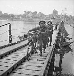
 Folding Boat Equipment Mk III bridge in North-west Europe (1944-45) | |
| Ancestor | Pontoon bridge |
|---|---|
| Carries | Pedestrians, Road vehicles |
| Span range | Short |
| Material | Timber, steel, canvas |
| Falsework required | None |
The Mk III version of the bridge was easy and quick to erect, which led in 1939 to its becoming the standard light bridging equipment, initially of the British armies, and the Allied armies during World War II. The Mk III equipment was capable of providing class 5 and 9 pontoon rafts, or a class 9 bridge. The equipment provided anchoring facilities and a full width trackway. It performed well even in fast currents and could be maintained and kept in use indefinitely.[3]
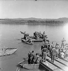
The FBE Mk III was used extensively during World War II by both British and American forces as the standard class 9 bridge. The FBE was widely used in both the European and South-East Asian theatres of war.
Configuration and deployment

The equipment provided the following capabilities:[4][5]
- Class 3 Tracked Raft, F.B.E. (ramp and deck parallel to the length of the boat).
- Class 5 Bridge, F.B.E., Mk. II.
- Class 5 Decked Raft Ferries, F.B.E. Mk. II and Mk. III. (ramp and deck perpendicular to the length of the boat).
- Class 9 Bridge, F.B.E., Mk. III.
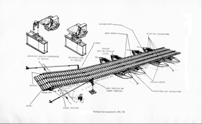
Bridges are constructed by joining rafts together. The connectors have limited articulation,[6] which permits the FBE Mk II bridge to carry a load of class 5 while an FBE MK III bridge can carry a vehicle of load class 9 (approximately 10 tons). The trestles are set up at each end and fix the end of the bridge to the bank. Anchors are placed at different positions along the length to anchor the bridge from being swept away by a changed current.
Parts

Folding Boat Equipment bridge consists of the following parts:[6]
- Folding boats. These could be used singly as an assault boat in combination of two to four boats to form a raft or ferry, or connected together with a deck trackway to form a bridge.
- Superstructure. For both rafts and bridge.
- Trestles. Used to anchor each end of the bridge.
- Anchors and anchor stores.
- Rafting gear and folding dinghies for assault boats.
Folding Boat

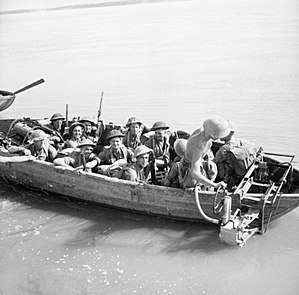
Each folding boat was 21 feet 10 inches long and 6 feet 8 inches wide, collapsible and could be carried flat on four-wheeled trailers or in bridging lorries. Three flat boats fitted on a trailer. Sixteen soldiers were required for manual carriage and launching a single boat. Each boat had a load capacity of 870 pounds and could accommodate 16 fully armed soldiers besides the boat commander and a crew of four.[5][6]
References
- "UK Military Bridging – Floating Equipment". Think Defence. 11 December 2011. Retrieved 1 March 2018.
- British War Production 1939-1945 – A Record. London: The Times Publishing Company Limited. 1945. pp. 74–75. Archived from the original on 30 June 2015. Retrieved 2 March 2018.
- A Military Encyclopedia – Based upon the Operations in the Italian Campaign (1943 - 1945). Italy: HQ 15 Army Group. 1 March 1945. p. 306. Archived from the original on 5 December 2012. Retrieved 1 March 2018.
- E-in-C's ( India) Pamphlet No 10 (1943) Notes on the Organization of that Part of the Corps of Indian Engineers under the E.in.C. G.H.Q. India. 1943. pp. 37–38. Retrieved 2 March 2018.
- Donald Portway (1940). Military Science Today. London: Oxford University Press. pp. 87–88. Retrieved 2 March 2018.
- Technical Manual 30-410 : Handbook on the British Army with Supplements on the Royal Air Force and Civilian Defense Organizations 1942. War Department, United States of America. 30 September 1942. pp. 56–57. Retrieved 3 March 2018.