Flexure
A flexure is a flexible element (or combination of elements) engineered to be compliant in specific degrees of freedom.[1] Flexures are a design feature utilized by design engineers (usually mechanical engineers) for providing adjustment or compliance in a design.
Flexure types
Most compound flexure designs are composed of 3 fundamental types of flexure:[2]
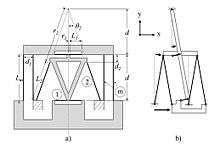
- Pin flexure- a thin bar or cylinder of material, constrains 3 degree of freedom when geometry matches a notch cutout.
- Blade flexure- thin sheet of material, constrains 4 degrees of freedom
- Notch flexure- thin cutout on both sides of a thick piece of material, constrains 5 degrees of freedom
| Pin Flexure | Blade Flexure | Notch Flexure |
|---|---|---|
 |  |  |
Since single flexure features are limited both in travel capability and degrees of freedom available, compound flexure systems are designed using combinations of these component features. Using compound flexures, complex motion profiles with specific degrees of freedom and relatively long travel distances are possible.
Design aspects
In the field of precision engineering (especially high-precision motion control), flexures have several key advantages. High precision alignment tasks might not be possible when friction or stiction are present.[4] Additionally, conventional bearings or linear slides often exhibit positioning hysteresis due to backlash and friction.[5] Flexures are able to achieve much lower resolution limits (in some cases measured in the nanometer scale), because they depend on bending and/or torsion of flexible elements, rather than surface interaction of many parts (as with a ball bearing). This makes flexures a critical design feature used in optical instrumentation such as interferometers.
Due to their mode of action, flexures are used for limited range motions and cannot replace long-travel or continuous-rotation adjustments.[6] Additionally, special care must be taken to design the flexure to avoid material yielding or fatigue, both of which are potential failure modes in a flexure design.
Design examples
- Living hinge: Flexure which acts as a hinge. Preferred for their simplicity, as they can be included as a feature in a single piece of material (as in a Tic Tac box's lid).
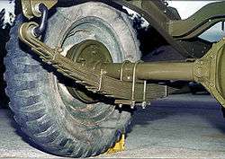
- Leaf spring: Leaf Springs are commonly used in vehicle suspensions. Leaf springs are an example of a flexure system with one compliant degree of freedom.
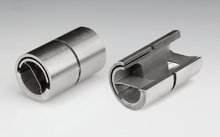
- Flex Pivot: Frictionless pivoting component, for use in precision alignment applications.[7]
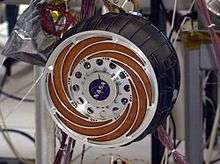
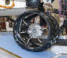
- NASA's Mars Exploration Rovers and the Mars Science Laboratory rover Curiosity have engineered flexures in their wheels which act as vibration isolation and suspension for the rovers.[8]
See also
References
- Thomas, Marcel. "Flexures". MIT Web. Retrieved 13 Feb 2017.
- "Flexural Encyclopedia". Bal-Tec. Retrieved 13 Feb 2017.
- Panas, Robert (7 Jul 2014). "Eliminating Underconstraint in Double Parallelogram Flexure Mechanisms". Lawrence Livermore National Laboratory. OSTI 1228007. Cite journal requires
|journal=(help) - Speich, John (5 Oct 1998). "Three-degree-of-freedom flexure-based manipulator for high-resolution spatial micromanipulation". SPIE Digital Library. Proc. SPIE Vol. 3519. Retrieved 14 February 2017.
- Zago, Lorenzo (Mar 1997). "Application of Flexure Structures to Active and Adaptive Opto-Mechanical Mechanisms" (PDF). University of Arizona Opto-Mechanical Papers Reference. Proc. SPIE Vol. 2871. Retrieved 13 February 2017.
- Salek, Mir (2008). "Flexure Mounts for High Resolution Optical Elements" (PPT). University of Arizona Opto-Mechanical Papers Reference. Retrieved 13 February 2017.
- "Free Flex Pivot Product line". Riverhawk Flex Pivots. Retrieved 13 February 2017.
- "Wheels in the Sky". NASA Jet Propulsion Laboratory. Retrieved 14 February 2017.