Electro Thermal Dynamic Stripping Process
Electro Thermal Dynamic Stripping Process (ET-DSP) is a patented in situ thermal environmental remediation technology, created by McMillan-McGee Corporation, for cleaning contaminated sites. ET-DSP uses readily available three phase electric power to heat the subsurface with electrodes. Electrodes are placed at various depths and locations in the formation. Electric current to each electrode is controlled continuously by computer to uniformly heat the target contamination zone.[2]
Difference between ERH and ET-DSP
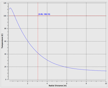
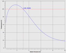
The difference between Electrical Resistance Heating (ERH) and ET-DSP is heat transfer due to convection. Water injected around the ET-DSP electrodes is heated and flows radially toward the vacuum extraction wells heating the formation in the process. The difference between ERH and ET-DSP is shown in the governing equations.
The governing equation for Electrical Resistance Heating (ERH) is given by,
where is the bulk heat capacity of the formation, T is the temperature, t is the time, is the thermal conductivity, is the electrical conductivity, I is the electric current and L is the electrode length.
The governing equation for Electro Thermal Dynamic Stripping Process (ET-DSP) is given by,
where is the density of water, is the specific heat of water and Q is the water injection rate.
Process Description [1]
ET-DSP electrodes are placed into the contaminated zone and are designed so that conventional three-phase power can be used to heat the soil. The distance between electrodes and their location is determined from the heat transfer mechanisms associated with vapor extraction, electrical heating, and fluid movement in the contaminated zone.
To determine the ideal pattern of electrode and extraction wells, a multi-phase, multi-component, 3-D thermal model is used to simulate the process. Numerical modeling is also used to design the power delivery system (PDS), the power requirements from the utility and the project capital requirements.
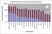
Electrical heating increases the temperature of the soil and groundwater by conducting current through the resistive connate water that fills the porosity of the soil. The increase in temperature raises the vapor pressure of volatile and semi-volatile contaminants, increasing their ability to volatilize and be recovered through conventional techniques such as soil vapor extraction.
Controlling The Heating Process [1]
ET-DSP utilizes a system of Time-Distributed Control (TDC) and Inter-Phase Synchronization (IPS) to control the power to the electrodes. This process controls the amount and timing of power sent to individual electrodes. If electrodes are in electrically resistive zones resulting in cold spots, the power to the electrodes can be increased in these areas to uniformly heat the formation. TDC and IPS controls the electrical sine wave of three-phase power to the millisecond such that each phase can be individually manipulated.
Numerical Modeling and Analysis [1]
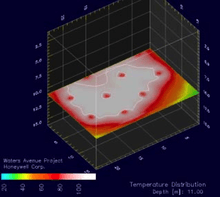
Prior to the implementation of the ET-DSP, site information such as surface infrastructure, surrounding land uses, short term site usage during remediation, subsurface lithology, depth to groundwater, plume characterization, type of contaminant, distribution of the contaminant and required time to attain target temperatures is collected. Numerical modeling and analysis simulation software combined with bench-scale experiments are used to determine the optimal thermal remediation strategy for the site.
Numerical modeling is important to determine optimum electrode configuration in terms of pattern type, shape, and separation; power supply requirements; power synchronization; optimal target temperature; and estimated time to attain the targeted temperature.
System Components
Power Delivery System (PDS) [1]
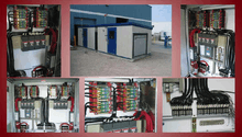
The Power Delivery System (PDS) is a computer controlled three-phase current transformer. The PDS can come in a range of KVA (kilovolt amp) ratings and are fully modular for plug and play applications. Each PDS is equipped with voltage tap settings that allow the voltage to be increased to the electrodes in formations with varying resistivity. ET-DSP can heat soil matrixes that range from tight clays to sands and rock.
Electrode Assembly [1]
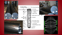
Electrodes for ET-DSP can be made in diameters up to 12”, lengths up to 10 feet long and are rated for up to 180 °C (356 °F) at more than 50 kW.
Using three phase power synchronization means that electrode patterns are not geometrically limited. The electrode assembly does not overheat the adjacent soils due to an imbedded water circulation system (cooling system) inside each electrode.
Electrodes are fabricated from high temperature resistant materials and are connected to the PDS. Each electrode is installed in a borehole packed with granular graphite which is compressed to the surface of the electrode. Conductors are run from each electrode back to the PDS and are can be installed either above or below grade.
Water Circulation System (WCS) [1]
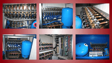
The water circulation system (WCS) provides water to the electrodes for the heat transfer due to convection and also cooling. The majority of the electrode’s energy is concentrated at the ends due to the current density. By injecting water at the ends, the water is heated to steam temperatures and is transported throughout the targeted volume. This process dynamically strips more slightly volatile organic compounds (SVOC’s) and other non-volatile contaminants such as creosote.
Water is distributed down the inside plumbing of the electrode, exiting the electrode through slots near the base and then washes over the outer surface of the metal. Some of the water is transported out into the subsurface soils to maintain the current pathway. The rest re-enters the electrode through upper slots and is then re-circulated back to the water holding tank.
The amount of water that is directed into the formation is dependent on the permeability of the subsurface soils. Typical injection rates into the formation are usually on the order of 0.1 to 0.2 gpm (gallon per minute) per electrode.
Extraction System [1]
Typically, high vacuum systems like liquid ring pumps, rotary positive blowers, and rotary vane blowers are utilized for the extraction systems. Extraction systems must be capable of handling water (multi-phase extraction) during the extraction process.
Heating can be conducted at and below the groundwater table, and larger quantities of groundwater are extracted and treated through the system. The extraction system is connected to the header and set up to extract both groundwater and hydrocarbon vapors from the subsurface within the electrode array. All recovered groundwater is transferred into the treatment system and then discharged. Contaminant vapors can be discharged into the ambient air or combusted, dependent on local regulatory requirements.
Extraction Wells and Header System [1]
Extraction wells are placed within the electrode array in order to maximize the recovery of the volatilizing hydrocarbons and are designed to control the groundwater to minimize the potential for offsite migration of the mobilized contaminant. Extraction wells are connected to an extraction header pipe, which is connected to the extraction system. Depending on the contaminant of concern either steel or an approved thermoplastic can be used in the header system.
Groundwater Treatment System [1]
Groundwater treatment systems remove dissolved contaminants and sediment from the groundwater. The treatment system typically consists of a sedimentation tank and an air stripper or granular activated carbon. Groundwater is transferred from the extraction system into the treatment system where the sediment and the dissolved-phase contaminants are removed. The clean effluent water is then discharged or removed by an approved method.
ET-DSP in the Athabasca Oil Sands
The Electro Thermal Dynamic Stripping Process (ET-DSP) is currently being used in the Athabasca Oil Sands to thermally recover bitumen and heavy oil by E-T Energy Limited. This electrothermal process converts electromagnetic energy into thermal energy by inducing current through the formation using excitor electrodes. Considerable control can be effected over the path taken by the currents and over the temperature profiles that will develop in the deposit by varying the operating frequency and excitor spacing.[3] Electrothermal processes are virtually free of problems related to very low initial formation injectivity, poor heat transfer and the near impossibility of adequately controlling the movement of injected fluids and gases.[3]
References
- ET-DSP Technical Description 3-Phase Electrical Resistive Soil Heating for the Remediation of Contaminated Soil and Groundwater
- McMillan-McGee Corp.
- [AOSTRA Technical Handbook on Oil Sands, Bitumens and Heavy Oils. Edited by Loren G. Hepler and Chu Hsi. Alberta Oil Sands Technology and Research Authority. Edmonton, Alberta, October 1989]