Ductwork airtightness
Ductwork airtightness can be defined as the resistance to inward or outward air leakage through the ductwork envelope (or ductwork shell). This air leakage is driven by differential pressures across the ductwork envelope due to the combined effects of stack and fan operation (in case of a mechanical ventilation system).
For a given HVAC system, the term ductwork refers to the set of ducts and fittings (tees, reducers, bends, etc.) that are used to supply the air to or extract the air from the conditioned spaces. It does not include components such as air handlers, heat recovery units, air terminal devices, coils. However, attenuators, dampers, access panels, etc. are a part of the ductwork even if they have more functions than conveying the air and are therefore also referred to as technical ductwork products.
Ductwork airtightness is the fundamental ductwork property that impacts the uncontrolled leakage of air through duct leaks.
Metrics
There are two major systems to classify ductwork airtightness, one based on European standards, the other based on ASHRAE standard 90.1-2010. Both are based on the leakage airflow rate at a given duct pressure divided by the product of the duct surface area and the same duct pressure raised to the power 0.65.
- In Europe, ductwork airtightness classes A to D are defined in European Standard EN 12237 [1] for circular ducts and EN 1507 [2] for rectangular ducts. Class A is the leakiest class. A parallel standard to EN 12237, EN 1507 and EN 1751 based on the same leakage classification is EN 15727 which applies to technical ductwork products and specifies the leakage requirements for technical ductwork products. The leakage test method for system commissioning is described in EN 12599. Airtightness classes for air handling units (L1 to L3) are defined in EN 1886. System standards, in particular EN 13779, give further recommendations for airtightness class selection for different purposes.[3]
- In the US, leakage classes 48, 24, 12, 6, 3 as defined by ASHRAE are commonly used; ASHRAE also gives recommended acceptance criteria based air leakage as a percentage of fan design airflow at maximum operating conditions.[4]
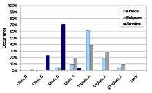
_TightVent_Classes_A-D_and_American_(ASHRAE)_TightVent_classes_CL3%2C_CL6%2C_etc.jpg)
Power law model of airflow through leaks
The relationship between pressure and leakage air flow rate is defined by the power law model between the airflow rate and the pressure difference across the ductwork envelope as follows:
qL=CL∆pn
where:
- qL is the volumetric leakage airflow rate expressed in L.s−1
- CL is the air leakage coefficient expressed in L.s−1.Pa−n
- ∆p is the pressure difference across the ductwork envelope expressed in Pa
- n is the airflow exponent (0.5 ≤ n ≤ 1)
This law enables to assess the airflow rate at any pressure difference regardless the initial measurement. Threshold limits in ductwork airtightness classifications usually assume an airflow exponent of 0,65.
Pressurization test
Ductwork airtightness levels can be measured by temporarily connecting a device (sometimes called a duct leakage tester to pressurize the ductwork including duct-mounted components. Air flow through the pressurizing device creates an internal, uniform, static pressure within the ductwork. The aim of this type of measurement is to relate the pressure differential across the ductwork to the air flow rate required to produce it. Generally, the higher the air flow rate required to produce a given pressure difference, the less airtight the ductwork. This pressurization technique is described in standard test methods such as EN 12237 and EN 1507, ASHRAE standard 90.1-2010. It is similar in principle to that used to characterize building airtightness.
Impact of ductwork airtightness
An airtight ductwork has several positive impacts:[5][6][7][8]
- secured air transport through the duct system;
- lower energy bills due to less heat loss and fan energy wastage to compensate the effect of the leaks;
- lower leakage airflow rates to/from unconditioned spaces (which can affect energy use, power demand, indoor air quality and comfort);
- easier airflow balancing;
- lower duct leakage noise.
Duct leakage affects more severely the energy efficiency of systems that include air heating or cooling.
Duct sealing or duct tightening
At construction stage, the airtightness of individual components depends on the design (rectangular or round ducts, pressed or segmented bends, etc.) and assembly (seam type and welding quality). Components with factory-fitted sealing devices (e.g., gaskets, clips) meant to ease and accelerate the installation process are widely used in Scandinavian countries.[8] A variety of techniques are widely used to tighten duct systems on site, including gaskets, tapes, sealing compound (mastic), internal duct lining, aerosol duct sealing. So-called "duct tapes" are often not suited for sealing ducts,[9][10] which explains why, in the US, the International Energy Conservation Code (IECC) requires any tape used on duct board or flexible ducts to be labeled in accordance with UL 181A or 181B.
Typical reasons for poor ductwork airtightness include:[11][12][5]
- inadequate or missing sealing media;
- worn tapes;
- poor workmanship around duct take-offs and fittings;
- ill-fitted components;
- physical damage.
Ductwork airtightness requirements
Sweden is often considered as a reference for airtight ducts: the requirements introduced in AMA (General material and workmanship specifications)[13] starting in 1950 have led to excellent ductwork airtightness on a regular basis in Sweden.[6][14]
In the US, there has been a significant amount of work showing energy saving potentials on the order of 20-30% in homes;[15] and 10-40% in commercial buildings with airtight ducts [16]
The ASIEPI project technical report [3] on building and ductwork airtightness estimated the heating energy impact of duct leakage in a ventilation system on the order of 0-5 kWh per m2 of floor area per year plus additional fan energy use for a moderately cold European region (2500 degree-days).
External links
References
- EN 12237:2003: "Ventilation for buildings - Ductwork - Strength and leakage of circular sheet metal ducts", 2003.
- EN 1507:2006: "Ventilation for buildings - Sheet metal air ducts with rectangular section - Requirements for strength and leakage", 2006
- G. Guyot, F. R. Carrié and P. Schild, “Project ASIEPI – Stimulation of good building and ductwork airtightness through EPBD,” 2010
- ASHRAE, "ASHRAE Handbook-Fundamentals- Chapter 21: Duct design." Atlanta, American Society of Heating, Refrigerating and Air-Conditioning Engineers, 2009.
- F. R. Carrié and P. Pasanen. "Chapter 3. Ductwork, hygiene and energy. In M. Santamouris and P. Wouters (eds). Building ventilation — The state of the art". pp. 107-136. Earthscan, UK 2006.
- J. Andersson. "Swedish experience with airtight ductwork". The REHVA European HVAC Journal: Special issue on airtightness. January 2013
- TightVent Europe. “Building and ductwork airtightness: Selected papers from the REHVA special journal issue on airtightness”. 2013
- C. Delmotte. "Airtightness of ventilation ducts". Air Infiltration and Ventilation Centre (AIVC) Ventilation Information Paper 01, 2003.
- M. Holladay. "Sealing Ducts: What’s Better, Tape or Mastic?". Green Building Advisor, 2010
- M. Sherman and I. Walker. "Can Duct Tape Take the Heat?". Home Energy Magazine Online, 1998
- Lawrence Berkeley National Laboratory (LBNL). "An Introduction to Residential Duct Systems". LBNL, 2003
- F. R. Carrié, J. Andersson, P. Wouters. "Improving ductwork—A time for tighter air distribution systems". Air Infiltration and Ventilation Centre. Coventry, UK., 1999.
- AMA VVS & Kyl 12. Allmän material- och arbetsbeskrivning för VVS- och Kyltekniska arbeten (General Material and Workmanship Specifications of HVAC installations). AB Svensk Byggtjänst, Stockholm 2012. (in Swedish).
- Peter G. Schild, Jorma Ralio. "Duct System Air Leakage - How Scandinavia tackled the problem", European project ASIEPI Paper 187, 2009, URL: http://www.buildup.eu/sites/default/files/content/P187_Duct_System_Air_Leakage_ASIEPI_WP5.pdf
- Energy Star. "Duct Sealing". Retrieved 5 May 2015.
- Lawrence Berkeley National Laboratory - Building Technology and Urban Systems Division (BTUS). "HVAC System Technologies". Retrieved 5 May 2015.