Jackshaft
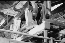
A jackshaft, also called a countershaft, is a common mechanical design component used to transfer or synchronize rotational force in a machine. A jackshaft is often just a short stub with supporting bearings on the ends and two pulleys, gears, or cranks attached to it. In general, a jackshaft is any shaft that is used as an intermediary transmitting power from a driving shaft to a driven shaft.

History
Jackshaft
The oldest uses of the term jackshaft appear to involve shafts that were intermediate between water wheels or stationary steam engines and the line shafts of 19th century mills.[1][2] In these early sources from New England mills in 1872 and 1880, the term "jack shaft" always appears in quotes. Another 1872 author wrote "Gear wheels are used in England to transmit the power of the engine to what is usually called the jack shaft."[3] By 1892, the quotes were gone, but the use remained the same.[4]
The pulleys on the jackshafts of mills or power plants were frequently connected to the shaft with clutches. For example, in the 1890s, the generating room of the Virginia Hotel in Chicago had two Corliss engines and five dynamos, linked through a jackshaft. Clutches on the jackshaft pulleys allowed any or all of the dynamos to be driven by either or both of the engines.[5] With the advent of chain-drive vehicles, the term jackshaft was generally applied to the final intermediate shaft in the drive train, either a chain driven shaft driving pinions that directly engaged teeth on the inside of the rims of the drive wheels,[6][7] or the output shaft of the transmission/differential that is linked by chain to the drive wheels.[8]
One of the first uses of the term jackshaft in the context of railroad equipment was in an 1890 patent application by Samuel Mower. In his electric-motor driven railroad truck, the motor was geared to a jackshaft mounted between the side frames. A sliding Dog clutch inside the jackshaft was used to select one of several gear ratios on the chain drive to the driven axle.[9] Later railroad jackshafts were generally connected to the driving wheels using side rods; see Jackshaft (locomotive) for details.
Countershaft
The term countershaft is somewhat older. In 1828, the term was used to refer to an intermediate horizontal shaft in a gristmill driven through gearing by the waterwheel and driving the millstones through bevel gears.[10] An 1841 textbook used the term to refer to a short shaft driven by a belt from the line shaft and driving the spindle of a lathe through additional belts. The countershaft and the lathe spindle each carried cones of different-diameter pulleys for speed control.[11] In 1872, this definition was given: "The term countershaft is applied to all shafts driven from the main line [shaft] when placed at or near the machines to be driven ..."[3]
- Modern uses
Modern jackshafts and countershafts are often hidden inside large machinery as components of the larger overall device.

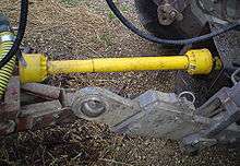
In farm equipment, a spinning output shaft on the rear of the vehicle is commonly referred to as the Power Take-Off or PTO, and the power-transfer shaft that is connected to it is commonly called a PTO shaft, but is also a jackshaft.
See also
References
- James Emerson, Report of Water-Wheel Tests at Lowell and Other Places, Journal of the Franklin Institute, Vol. LXIII, No. 3 (March, 1872); pages 177-178.
- Holyoke Warter Power Co., Experiments with Gears, Belts and Draft Tubes, Holyoke Hydrodynamic Experiments, Weaver Shipman and Co., Springfield, Mass., 1880; pages 73-76.
- Coleman Sellers, Transmission of Motion, Journal of the Franklin Institute, Vol. LXIV, No. 5 (Nov. 1872); pages 305-319, countershaft is defined on page 314, jack shaft on page 316.
- Robert Grimshaw, Drive for Power Transmission, Cassier's Magazine Vol. II, No. 9 (July 1892); pages 219-224, see particularly figure 1 and the discussion of it on pages 223-224.
- John J. Flather, Rope-Driving: A treatise on the transmission of power by means of fibrous ropes, Wiley, New York, 1895; pages 42-43. Fig. 21 shows part of the jack-shaft.
- The Darling Steam Carriage, The Horseless Age, Vol. 5, No. 2 (Oct. 11, 1899); page 6.
- Some New American Steam Carriages, The Motor Car Journal, Vol I, No. 36 (Nov. 10, 1899); page 565.
- The Grout Steam Tonneau, Cycle and Automobile Trade Journal Vol II, No. 8 (Feb 1, 1902) ;pages 55-56.
- Samuel E. Mower, Electric-Motor Mechanism, U.S. Patent 450,970, issued Apr. 21, 1891.
- James Hindman and William Hindman, Improvement in the Grist Mill, The American Journal of Improvements in the Useful Arts and Mirror of the Patent Office in the United States, Vol I, No. 3 (July, Aug. and Sept. 1828); page 324. This reads like a patent application, there is no record of a corresponding patent.
- Robert Willis, Part the Third, Chapter II -- To Alter the Velocity Ratio by Determinate Changes, Principles of Mechanism Designed for the Use of Students in the Universities and for Engineering Students Generally, John W. Parker, London, 1841; page 433.