Contourlet
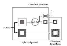
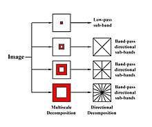
Contourlets form a multiresolution directional tight frame designed to efficiently approximate images made of smooth regions separated by smooth boundaries. The contourlet transform has a fast implementation based on a Laplacian pyramid decomposition followed by directional filterbanks applied on each bandpass subband.
Contourlet transform
Introduction and motivation
In the field of geometrical image transforms, there are many 1-D transforms designed for detecting or capturing the geometry of image information, such as the Fourier and wavelet transform. However, the ability of 1-D transform processing of the intrinsic geometrical structures, such as smoothness of curves, is limited in one direction, then more powerful representations are required in higher dimensions. The contourlet transform which was proposed by Do and Vetterli in 2002, is a new two-dimensional transform method for image representations. The contourlet transform has properties of multiresolution, localization, directionality, critical sampling and anisotropy. Its basic functions are multiscale and multidimensional. The contours of original images, which are the dominant features in natural images, can be captured effectively with a few coefficients by using contourlet transform.
The contourlet transform is inspired by the human visual system and Curvelet transform which can capture the smoothness of the contour of images with different elongated shapes and in variety of directions.[1] However, it is difficult to sampling on a rectangular grid for Curvelet transform since Curvelet transform was developed in continuous domain and directions other than horizontal and vertical are very different on rectangular grid. Therefore, the contourlet transform was proposed initially as a directional multiresolution transform in the discrete domain.
Definition

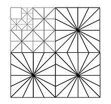
The contourlet transform uses a double filter bank structure to get the smooth contours of images. In this double filter bank, the Laplacian pyramid (LP) is first used to capture the point discontinuities, and then a directional filter bank (DFB) is used to form those point discontinuities into linear structures.[2]
The Laplacian pyramid (LP) decomposition only produce one bandpass image in a multidimensional signal processing, that can avoid frequency scrambling. And directional filter bank (DFB) is only fit for high frequency since it will leak the low frequency of signals in its directional subbands. This is the reason to combine DFB with LP, which is multiscale decomposition and remove the low frequency. Therefore, image signals pass through LP subbands to get bandpass signals and pass those signals through DFB to capture the directional information of image. This double filter bank structure of combination of LP and DFB is also called as pyramid directional filter bank (PDFB), and this transform is approximate the original image by using basic contour, so it is also called discrete contourlet transform.[3]
The properties of discrete contourlet transform [3]
1). If perfect-reconstruction filters are used for both the LP decomposition and DFB, then the discrete contourlet transform can reconstruct the original image perfectly, which means it provides a frame operator.
2). If orthogonal filters are used for both the LP decomposition and DFB, then the discrete contourlet transform provides a tight frame which bounds equal to 1.
3). The upper bound for the redundancy ratio of the discrete contourlet transform is .
4). If the pyramidal level of LP applies to level DFB, the basis images of the contourlet transform have the size of ≈ and ≈ .
5). When FIR is used, the computational complexity of the discrete contourlet transform is for N-pixel images.
Nonsubsampled contourlet transform
Motivation and applications
The contourlet transform has a number of useful features and qualities, but it also has its flaws. One of the more notable variations of the contourlet transform was developed and proposed by da Cunha, Zhou and Do in 2006. The nonsubsampled contourlet transform (NSCT) was developed mainly because the contourlet transform is not shift invariant.[4] The reason for this lies in the up-sampling and down-sampling present in both the Laplacian Pyramid and the directional filter banks. The method used in this variation was inspired by the nonsubsampled wavelet transform or the stationary wavelet transform which were computed with the à trous algorithm.[4]
Though the contourlet and this variant are relatively new, they have been used in many different applications including synthetic aperture radar despeckling,[5] image enhancement[6] and texture classification.[7]
Basic concept

To retain the directional and multiscale properties of the transform, the Laplacian Pyramid was replaced with a nonsubsampled pyramid structure to retain the multiscale property, and a nonsubsampled directional filter bank for directionality. The first major notable difference is that upsampling and downsampling are removed from both processes. Instead the filters in both the Laplacian Pyramid and the directional filter banks are upsampled. Though this mitigates the shift invariance issue a new issue is now present with aliasing and the directional filter bank. When processing the coarser levels of the pyramid there is potential for aliasing and loss in resolution. This issue is avoided though by upsampling the directional filter bank filters as was done with the filters from the pyramidal filter bank.[4]
The next issue that lies with this transform is the design of the filters for both filter banks. According to the authors there were some properties that they desired with this transform such as: perfect reconstruction, a sharp frequency response, easy implementation and linear-phase filters.[4] These features were implemented by first removing the tight frame requirement and then using a mapping to design the filters and then implementing a ladder type structure. These changes lead to a transform that is not only efficient but performs well in comparison to other similar and in some cases more advanced transforms when denoising and enhancing images.
Variations of the contourlet transform
Wavelet-based contourlet transform

Although the wavelet transform is not optimal in capturing the 2-D singularities of images, it can take the place of LP decomposition in the double filter bank structure to make the contourlet transform a non-redundant image transform.[8] The wavelet-based contourlet transform is similar to the original contourlet transform, and it also consists of two filter bank stages. In the first stage, the wavelet transform is used to do the sub-band decomposition instead of the Laplacian pyramid (LP) in the contourlet transform. And the second stage of the wavelet-based contourlet transform is still a directional filter bank (DFB) to provide the link of singular points. One of the advantages to the wavelet-based contourlet transform is that the wavelet-based contourlet packets are similar to the wavelet packets which allows quad-tree decomposition of both low-pass and high-pass channels and then apply the DFB on each sub-band.
The hidden Markov tree (HMT) model for the contourlet transform
Based on the study of statistics of contourlet coefficients of natural images, the HMT model for the contourlet transform is proposed. The statistics show that the contourlet coefficients are highly non-Gaussian, high interaction dependent on all their eight neighbors and high inter-direction dependent on their cousins. Therefore, the HMT model, that captures the highly non-Gaussian property, is used to get the dependence on neighborhood through the links between the hidden states of the coefficients.[9] This HMT model of contourlet transform coefficients has better results than original contourlet transform and other HMT modeled transforms in denoising and texture retrieval, since it restores edges better visually.
Contourlet transform with sharp frequency localization
An alternative or variation of the contourlet transform was proposed by Lu and Do in 2006. This new proposed method was intended as a remedy to fix non-localized basis images in frequency.[10] The issue with the original contourlet transform was that when the contourlet transform was used with imperfect filter bank filters aliasing occurs and the frequency domain resolution is affected. There are two contributing factors to the aliasing, the first is the periodicity of 2-D frequency spectra and the second is an inherent flaw in the critical sampling of the directional filter banks.[10] This new method mitigates these issues by changing the method of multiscale decomposition. As mentioned before, the original contourlet used the Laplacian Pyramid for multiscale decomposition. This new method as proposed by Lu and Do uses a multiscale pyramid that can be adjusted by applying low pass or high pass filters for the different levels.[10] This method fixes multiple issues, it reduces the amount of cross terms and localizes the basis images in frequency, removes aliasing and has proven in some instances more effective in denoising images. Though it fixes all of those issues, this method requires more filters than the original contourlet transform and still has both the up-sampling and down-sampling operations meaning it is not shift-invariant.
Image enhancement based on nonsubsampled contourlet transform
In prior studies the contourlet transform has proven effective in the denoising of images but in this method the researchers developed a method of image enhancement. When enhancing images preservation and the enhancement of important data is of paramount importance. The contourlet transform meets this criterion to some extent with its ability to denoise and detect edges.[3] This transform first passes the image through the multiscale decomposition by way of the nonsubsampled laplacian pyramid. After that, the noise variance for each sub-band is calculated and relative to local statistics of the image it is classified as either noise, a weak edge or strong edge. The strong edges are retained, the weak edges are enhanced and the noise is discarded. This method of image enhancement significantly outperformed the nonsubsampled wavelet transform (NSWT) both qualitatively and quantitatively.[6] Though this method outperformed the NSWT there still lies the issue of the complexity of designing adequate filter banks and fine tuning the filters for specific applications of which further study will be required.[6]
Applications
Image Denoising
Image Enhancement
Image Restoration
Image Despeckling
See also
- Wavelet
- Multiresolution analysis
- Scale space
- Bandelets
- Curvelets
- Multiscale decomposition
- Directional decomposition
- Pyramid Directional Filter Banks
- Basis Functions
References
- E. J. Candès and D. L. Donoho, “Curvelets – a surprisingly effective nonadaptive representation for objects with edges,” in Curve and Surface Fitting, A. Cohen, C. Rabut, and L. L. Schumaker, Eds. Saint-Malo: Vanderbilt University Press, 1999.
- M. N. Do, Directional multiresolution image representations. PhD thesis, EPFL, Lausanne, Switzerland, Dec. 2001.
- M. N. Do and M. Vetterli, "The contourlet transform: an efficient directional multiresolution image representation", IEEE Transactions on Image Processing, vol. 14, no. 12, pp. 2091–2106, Dec. 2005.-->
- L.da Cunha, Jianping Zhou, and Minh N. Do, “The nonsubsampled contourlet transform: theory, design, and applications,” IEEE Transactions on Image Processing, Vol. 15, No. 10, pp. 3089–3101, 2006.
- W. Ni, B. Guo, Y. Yan, and L. Yang, “Speckle suppression for SAR images based on adaptive shrinkage in contourlet domain,” in Proc. 8th World Congr. Intell. Control Autom., vol. 2. 2006, pp. 10017–10021.
- Ma Y., Xie J., Luo J., "Image Enhancement Based on Nonsubsampled Contourlet Transform", International Conference on Information Assurance and Security, 2009., pp. 1–4
- Li.S, Fu.X, Yang.B, “Nonsubsampled Contourlet Transform for Texture Classifications using Support Vector Machines,” IEEE ICNSC, pp. 1654– 1657, 2008.
- Ramin Eslami and Hayder Radha,"wavelet-based contourlet transform and its application to image coding,” in Proceedings of the IEEE International Conference on Image Processing (ICIP’04), IEEE Signal Processing Society, Vol. 5,pp. 3189 - 3192
- D. D.-Y. Po and M. N. Do, “Directional multiscale modeling of images using the contourlet transform,” IEEE Trans. Image Process., vol. 15, no. 6, pp. 1610–1620, Jun. 2006.
- Y. Lu and M. N. Do, “A new contourlet transform with sharp frequency localization,” IEEE Int. Conf. Image Processing, Atlanta, GA, Oct. 2006., pp. 1–4
External links
- The Contourlet Toolbox (in Matlab)