Continuous cooling transformation
A continuous cooling transformation (CCT) phase diagram is often used when heat treating steel.[1] These diagrams are used to represent which types of phase changes will occur in a material as it is cooled at different rates. These diagrams are often more useful than time-temperature-transformation diagrams because it is more convenient to cool materials at a certain rate (temperature-variable cooling), than to cool quickly and hold at a certain temperature (isothermal cooling).

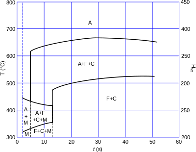
Continuous cooling transformation diagram of EN S355 (ASTM A-572 Grade 50, warranted yield stress 355 MPa) for welding (fast cooling, linear scale).
Types of continuous cooling diagrams
There are two types of continuous cooling diagrams drawn for practical purposes.
- Type 1: This is the plot beginning with the transformation start point, cooling with a specific transformation fraction and ending with a transformation finish temperature for all products against transformation time for each cooling curve.
- Type 2: This is the plot beginning with the transformation start point, cooling with specific transformation fraction and ending with a transformation finish temperature for all products against cooling rate or bar diameter of the specimen for each type of cooling medium.
gollark: Please read my network security docs.
gollark: https://wiki.computercraft.cc/Network_security
gollark: REDNET IS A THIN WRAPPER OVER THE LOWER LEVEL MODEM PERIPHERAL
gollark: THAT CAN BE SPOOFED TRIVIALLY!
gollark: WRONG!
See also
| Wikimedia Commons has media related to Continuous cooling transformation diagrams. |
- Isothermal transformation
- Phase diagram
References
- Transformation diagrams (CCT & TTT), archived from the original on 2008-04-18, retrieved 2008-04-17.
This article is issued from Wikipedia. The text is licensed under Creative Commons - Attribution - Sharealike. Additional terms may apply for the media files.