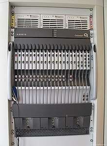
Cable modem termination system
A cable modem termination system or CMTS is a piece of equipment, typically located in a cable company's headend or hubsite, which is used to provide high speed data services, such as cable Internet or Voice over Internet Protocol, to cable subscribers. A CMTS provides many of the same functions provided by the DSLAM in a DSL system.

Connections
In order to provide high speed data services, a cable company will connect its headend to the Internet via very high capacity data links to a network service provider. On the subscriber side of the headend, the CMTS enables the communication with subscribers' cable modems. Different CMTSs are capable of serving different cable modem population sizes—ranging from 4,000 cable modems to 150,000 or more, depending in part on traffic. A given headend may have between 1-12 CMTSs to service the cable modem population served by that headend or HFC hub.
One way to think of a CMTS is to imagine a router with Ethernet interfaces (connections) on one side and coaxial cable RF interfaces on the other side. The RF/coax interfaces carry RF signals to and from the subscriber's cable modem.
In fact, most CMTSs have both Ethernet interfaces (or other more traditional high-speed data interfaces like SONET) as well as RF interfaces. In this way, traffic that is coming from the Internet can be routed (or bridged) through the Ethernet interface, through the CMTS and then onto the RF interfaces that are connected to the cable company's hybrid fiber coax (HFC). The traffic winds its way through the HFC to end up at the cable modem in the subscriber's home. Traffic from a subscriber's home system goes through the cable modem and out to the Internet in the opposite direction.
CMTSs typically carry only IP traffic. Traffic destined for the cable modem from the Internet, known as downstream traffic, is carried in IP packets encapsulated according to DOCSIS standard. These packets are carried on data streams that are typically modulated onto a TV channel using either 64-QAM or 256-QAM versions of quadrature amplitude modulation.
Upstream data (data from cable modems to the headend or Internet) is carried in Ethernet frames encapsulated inside DOCSIS frames modulated with QPSK, 16-QAM, 32-QAM, 64-QAM or 128-QAM using TDMA, ATDMA or S-CDMA frequency sharing mechanisms. This is done at the "subband" or "return" portion of the cable TV spectrum (also known as the "T" channels), a much lower part of the frequency spectrum than the downstream signal, usually 5 - 42 MHz in DOCSIS 2.0 or 5 - 60 MHz in EuroDOCSIS.
A typical CMTS allows a subscriber's computer to obtain an IP address by forwarding DHCP requests to the relevant servers. This DHCP server returns, for the most part, what looks like a typical response including an assigned IP address for the computer, gateway/router addresses to use, DNS servers, etc.
The CMTS may also implement some basic filtering to protect against unauthorized users and various attacks. Traffic shaping is sometimes performed to prioritize application traffic, perhaps based upon subscribed plan or download usage and also to provide guaranteed Quality of service (QoS) for the cable operator's own PacketCable-based VOIP service. However, the function of traffic shaping is more likely done by a Cable Modem or policy traffic switch. A CMTS may also act as a bridge or router.
A customer's cable modem cannot communicate directly with other modems on the line. In general, cable modem traffic is routed to other cable modems or to the Internet through a series of CMTSs and traditional routers. However, a route could conceivably pass through a single CMTS.
Architectures
A CMTS can be broken down into two different architectures, Integrated CMTS (I-CMTS) or Modular (M-CMTS). There are both pros and cons to each type of architecture.
Modular CMTS (M-CMTS)
In an M-CMTS solution the architecture is broken up into two components. The first part is the Physical Downstream component (PHY) which is known as the Edge QAM (EQAM). The second part is the IP networking and DOCSIS MAC Component which is referred to as the M-CMTS Core. There are also several new protocols and components introduced with this type of architecture. One is the DOCSIS Timing Interface, which provides a reference frequency between the EQAM and M-CMTS Core via a DTI Server. The second is the Downstream External PHY Interface (DEPI). The DEPI protocol controls the delivery of DOCSIS frames from the M-CMTS Core to the EQAM devices [1] Some of the challenges that entail an M-CMTS platform are increased complexity in RF combining and an increase in the number of failure points. One of the benefits of an M-CMTS architecture is that it is extremely scalable to larger numbers of downstream channels.[2]
Manufacturers
Current
- ARRIS Group
- C9 Networks
- Catapult Technologies
- Coaxial Networks Inc.
- Casa Systems
- Cisco Systems
- Chongqing Jinghong
- Damery sa
- Gainspeed (Nokia company)
- WISI Communications GmbH
- Kathrein
- Suma Scientific
- Huawei Technologies
- Harmonic Inc.
- Teleste
Historical
- 3COM (Acquired by HP)
- Broadband Access Systems (Acquired by ADC Telecommunications)
- ADC Telecommunications (CMTS business acquired by BigBand Networks)
- BigBand Networks (Exited CMTS business, remaining business later acquired by ARRIS)
- Cadant (Acquired by ARRIS)
- Com21 (CMTS business acquired by ARRIS)
- RiverDelta (Acquired by Motorola)
- Terayon (Acquired by Motorola)
- Pacific Broadband Communications (Acquired by Juniper Networks)
- Juniper Networks (Exited CMTS business)
- Motorola (Acquired by ARRIS)
- Daphne sa (Acquired by Damery sa)
See also
References
- "Data-Over-Cable Service Interface Specifications Modular Headend Architecture" (PDF). www.cablelabs.com. Archived from the original (PDF) on 2015-02-27. Retrieved 2015-02-27.
- "CMTS Architectures". volpefirm.com.