Bifilar coil
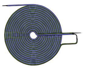
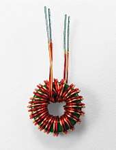
A bifilar coil is an electromagnetic coil that contains two closely spaced, parallel windings. In engineering, the word bifilar describes wire which is made of two filaments or strands. It is commonly used to denote special types of winding wire for transformers. Wire can be purchased in bifilar form, usually as different colored enameled wire bonded together. For three strands, the term trifilar coil is used.


Description and applications
|
Some bifilars have adjacent coils in which the convolutions are arranged so that the potential difference is magnified (i.e., the current flows in same parallel direction). Others are wound so that the current flows in opposite directions. The magnetic field created by one winding is therefore equal and opposite to that created by the other, resulting in a net magnetic field of zero (i.e., neutralizing any negative effects in the coil). In electrical terms, this means that the self-inductance of the coil is zero.
The bifilar coil (more often called the bifilar winding) is used in modern electrical engineering as a means of constructing wire-wound resistors with negligible parasitic self-inductance.[1]

A different type of bifilar coil is used in some relay windings and transformers used for a switched-mode power supply to suppress back-emf. In this case, the two wire coils are closely spaced and wound in parallel but are electrically isolated from each other. The primary coil is driven to operate the relay, and the secondary coil is short-circuited inside the case. When the current through the primary is interrupted, as happens when the relay is switched off, most of the magnetic energy is intercepted by the secondary coil which converts it to heat in its internal resistance. This is only one of several methods of absorbing the energy from the primary coil before it can damage the device (usually a vulnerable semiconductor) that drives the relay. The main disadvantage of this method is that it greatly increases the switching time of the relay.
When used in a switching transformer, one winding of the bifilar coil is used as a means of removing the energy stored in the stray magnetic flux which fails to link the primary coil to the secondary coil of the transformer. Because of their proximity, the wires of the bifilar coil both "see" the same stray magnetic flux. One wire is clamped to ground usually by a diode so that when the other "primary" wire of the bifilar coil no longer has a voltage applied across it by the switching transistor, the stray magnetic flux generates a current in the clamping coil with the primary side voltage appearing across it, causing an equal voltage to appear across the primary winding. If this clamping coil was not used, the stray magnetic flux would attempt to force a current to flow through the primary wire. Since the primary wire is switched off and the switching transistor is in a high resistance state, the high voltage which would appear on the semiconductor switching transistor would exceed its electrical breakdown or even damage it.
Bifilar coils impose an inductance in the common mode, but impose no inductance in the differential mode. Coils in such a combination are widely used to eliminate ingress or egress of common mode signals from electronic signalling circuits. This arrangement is used in transmission and reception magnetics of Ethernet cables[2] and conspicuously in the form of a ferrite bead clamped to the outside of USB, laptop power supply and HDMI cables.
History
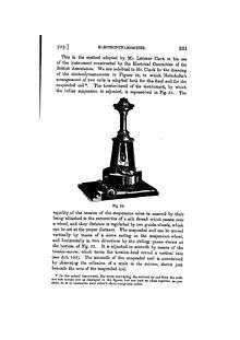
German physicist Wilhelm Eduard Weber made use of the bifilar coil in his 1848 electrodynamometer.[3] Large examples were used in inventor Daniel McFarland Cook's 1871 "Electro-Magnetic Battery"[4] and Nikola Tesla's high frequency power experiments at the end of the 1800s.[5] Nikola Tesla patented the Bifilar Coil on January 9, 1894, referring to it as a “Coil for Electro Magnets”.[5]
See also

- Ayrton-Perry winding
- Basket winding
- Mirror bifilar electrodynamometer
References
- "Non-inductive Wirewound Resistors" (PDF). 2010. Retrieved 7 April 2015.
- "10/100Base-T Single Port Surface Mount Magnetics With Various Turns Ratios" (PDF). Archived from the original (PDF) on 31 July 2012. Retrieved 7 April 2015.
- Annual of Scientific Discovery, Gould and Lincoln, 1851, page 125
- Andersen, Kent (2013). Saving Planet Earth : A Practical Hands on Approach. p. 47. ISBN 978-1-257-20704-6.
- United States patent 512,340 of 1894
External links
- Tesla's patent
- Bifilar relay coils
- Resistance coils for alternating current work By Harvey Lincoln Curtis, Frederick Warren Grover, United States. Bureau of standards. Reprint no. 177.