Bedform
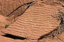
A bedform is a feature that develops at the interface of fluid and a moveable bed, the result of bed material being moved by fluid flow. Examples include ripples and dunes on the bed of a river. Bedforms are often preserved in the rock record as a result of being present in a depositional setting. Bedforms are often characteristic to the flow parameters,[1] and may be used to infer flow depth and velocity, and therefore the Froude number.

Bedforms Initiation
Bedforms are omnipresent in many environments (e.g., fluvial, eolian, glaciofluvial, deltaic and deep sea), although there is still some debate on how they develop. There are two separate, though not mutually exclusive,[2] models of bedform initiation: defect initiation and instantaneous initiation.
Defect Initiation
The defect theory proposes that the turbulent sweeps that are generated in turbulent flows [3][4] entrain sediment[5] that upon deposition generates defects in a non-cohesive material. These deposits then propagate downstream via a flow separation process, thus developing bedform fields. The origin of the defects is thought to be linked to packets of hairpin vortex structures.[6] These coherent turbulent structures give rise to entrainment corridors on the mobile bed, forming grain lineations that interact with the low-speed streaks generating an agglomeration of grains. Once a critical height of grains is reached, flow separation occurs over the new structure. Sediment will be eroded close from the reattachment point and deposited downstream creating a new defect. This new defect will thus induce formation of another defect and the process will continue, propagating downstream while the accumulations of grains quickly evolve into small bedforms.
Instantaneous Initiation
In general, the defect propagation theory plays a bigger role at low sediment transport rates since for high rates defects maybe washed away and bedforms generally initiated across the entire bed spontaneously.[7][8] Venditti et al. (2005)[7]:1 report that instantaneous initiation begins with the formation of a cross-hatch pattern, which leads to chevron-shaped forms that migrate independently of the pattern structure. This chevron-like structure reorganizes to form the future crest lines of the bedforms. Venditti et al. (2006),[8]:1 based on the earlier model by Liu (1957), proposed that instantaneous initiation is a manifestation of an interfacial hydrodynamic instability of Kelvin-Helmholtz type between a highly active pseudofluid sediment layer and the fluid above it. In addition, Venditti et al. (2005)[7]:2 imply that there is no linkage between the instantaneous initiation and coherent turbulent flow structures, since spatially- and temporally-random events should lock in place to generate the cross-hatch pattern. Moreover, there is no clear explanation of the effect of turbulence in the formation of bedforms since bedforms may also occur under laminar flows . It is important to note, that laminar-generated bedform studies used the temporally-averaged flow conditions to determine the degree of turbulence, indicating Reynolds number in the laminar regime. However, instantaneous process, such as burst and sweeps, which are infrequent at low Reynolds number but still present, can be the driving mechanisms to generate the bedforms. The generation of bedforms in laminar flows is still a topic of debate within the scientific community, since if true, it suggests that there should be other processes for defect development other than the one suggested by Best (1992).[6]:1 This alternative model for bedform development at low sediment transport rates should explain the generation of defects and bedforms for cases where the flow is not turbulent.
Bedform phase diagrams
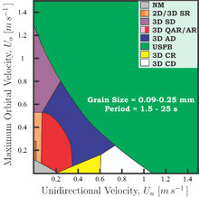
Phase or stability diagrams are defined as graphs that show the regimes of existence of one or more stable bed states. The stability of the bed can be defined when the bedform is in equilibrium and does not change in time for the same flow condition. This invariance over time must not be confused with a static morphology or frozen equilibrium; on the contrary, the bed moves and adjusts in a dynamic equilibrium with the flow and sediment transport for that particular condition. These phase diagrams [1]:1[9] are used for two main purposes: i) for prediction of bed states in a known flow and sediment transport condition, and, ii) as a tool for the reconstruction of paleoenvironments from a known bed state or sedimentary structure. Despite the great utility of such diagrams, they are very difficult to construct, making them either incomplete or very hard to interpret. This complexity lies in the number of variables needed to quantify the system.

Bedforms vs. flow
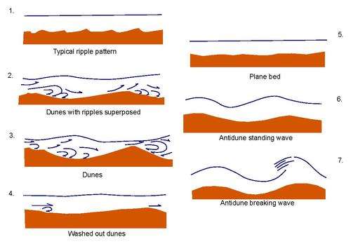
Typical unidirectional bedforms represent a specific flow velocity, assuming typical sediments (sands and silts) and water depths, and a chart such as below can be used for interpreting depositional environments,[10] with increasing water velocity going down the chart.
| Flow Regime | Bedform | Preservation Potential | Identification Tips |
| Lower | |||
| Lower plane bed | High | Flat laminae, almost lack of current | |
| Ripple marks | High | Small, cm-scale undulations | |
| Sand waves | Medium to low | Rare, longer wavelength than ripples | |
| Dunes/Megaripples | High | Large, meter-scale ripples | |
| Upper | |||
| Upper plane bed | High | Flat laminae, +/- aligned grains (parting lineations) | |
| Antidunes | Low | Water in phase with bedform, low angle, subtle laminae | |
| Pool and chute | Very low | Mostly erosional features | |
This chart is for general use, because changes in grain size and flow depth can change the bedform present and skip bedforms in certain scenarios. Bidirectional environments (e.g. tidal flats) produce similar bedforms, but the reworking the sediments and opposite directions of flow complicates the structures.
This bed form sequence can also be illustrated diagrammatically:

Types of Bedforms
Lower Plane Bed
"Lower plane bed" refers to the flat configuration the bed of a river that is produced in via low rates of sediment transport.[11]
Upper Plane Bed
"Upper plane bed" features are flat and characterized by a unidirectional flow with high rates of sediment transport as both bed load and suspended load. Upper plane bed conditions can produce parting current lineations, which are typically subtle streaks on the bed surface due to the high energy flow.[11]
References
- Southard, J B (1991). "Experimental Determination of Bed-Form Stability". Annual Review of Earth and Planetary Sciences. 19: 423–455. Bibcode:1991AREPS..19..423S. doi:10.1146/annurev.ea.19.050191.002231.
- Perillo, Mauricio M. (2013). Flow, sediment transport and bedforms under combined flows (Ph.D.). University of Illinois at Urbana-Champaign.
- Willmarth, W. W.; Lu, S. S. (1972). "Structure of the reynolds stress near the wall". Journal of Fluid Mechanics. 55 (1): 65–92. Bibcode:1972JFM....55...65W. doi:10.1017/S002211207200165X.
- Lu, S. S.; Willmarth, W. W. (1973). "Measurements of the structure of the reynolds stress in a turbulent boundary layer". Journal of Fluid Mechanics. 60 (3): 481–511. Bibcode:1973JFM....60..481L. doi:10.1017/S0022112073000315.
- Grass, A. J. (1983). "The influence of boundary layer turbulence on the mechanics of sediment transport". In Sumer, B. M.; Muller, A. (eds.). Mechanics of Sediment Transport. A. A. Balkema. pp. 3–18.
- Best, J. L. (1992). "On the entrainment of sediment and initiation of bed defects: insights from recent developments within turbulent boundary layer research". Sedimentology. 39 (5): 797–811. Bibcode:1992Sedim..39..797B. doi:10.1111/j.1365-3091.1992.tb02154.x.
- Venditti, J. G.; Church, M. A.; Bennett, S. J. (2005). "Bed form initiation from a flat sand bed". Journal of Geophysical Research. 110: F01009. Bibcode:2005JGRF..110.1009V. doi:10.1029/2004jf000149.
- Venditti, J. G.; Church, M. A.; Bennett, S. J. (2006). "On interfacial instability as a cause of transverse subcritical bed forms". Water Resources Research. 42: W07423. Bibcode:2006WRR....42.7423V. doi:10.1029/2005wr004346.
- Perillo, Mauricio M.; Best, James L.; Garcia, Marcelo H. (2014). "A new phase diagram for combined-flow bedforms". Journal of Sedimentary Research. 84: 301–313. Bibcode:2014JSedR..84..301P. doi:10.2110/jsr.2014.25.
- Prothero, D. R. and Schwab, F., 1996, Sedimentary Geology, pg. 45-49, ISBN 0-7167-2726-9
- Klaus K.E. Neuendorf; James P. Mehl Jr.; Julia A. Jackson, eds. (2005). Glossary of geology. Alexandria: American Geological Institute. p. 382. ISBN 0-922152-76-4.