Barring engine
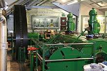
A barring engine is a small engine, usually a steam engine, that forms part of the installation of a large stationary steam engine. It is used to turn the main engine to a favourable position from which it can be started. If the main engine has stopped close to its dead centre it is unable to restart itself.[1]
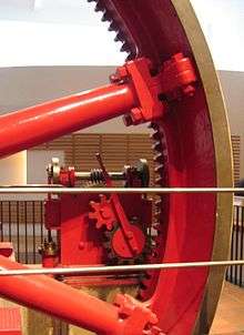
Note the drive by internal gear teeth.
Barring may also be done to turn the engine over slowly (unloaded) for maintenance, or to prevent belt drives being left too long in one position and taking a "set".
Development
The first barring engines or barring gear were manual. At their simplest, they were a hefty engineer with a crowbar (hence the term "barring"). The engine's flywheel could be provided with a series of holes or teeth and a roller fulcrum set into the frame at a convenient place. Later manual barring engines had geared drives and a crank handle. With suitable reduction gears, even very large engines could be barred by hand. This only needed to be done once a day and was not a hurried operation, so speed was not crucial.
Where a steam barring engine was used, this was a small twin-cylinder engine (to avoid its own dead centre problems) with a reduction gear of high ratio, usually involving a worm gear. Final drive was by a pinion gear engaging temporarily with the teeth or barring holes cut into the rim of the main flywheel. The drive pinion was arranged on a swinging link so that it was thrown out-of-mesh automatically, once the main engine started to rotate at full speed. As the ratio was perhaps 1000:1 and the main engine ran at 60 rpm, this would otherwise have been a disastrous overspeed.[1] Some engines instead used a final pinion on a helical spline, similar to that later used for the starters of internal combustion engines: once the main engine started, the pinion would be thrown out of engagement axially along this spline as the flywheel over-speeded the pinion relative to the shaft.[2]
As mill engines became more powerful, from around 1870 there was a shift from single belt drives to multiple rope drives.[3] The barring engine needed to turn these rope drives over as well (although they were disconnected from the machinery at the remote end) and a simple manual gear was no longer sufficient. Around 1881–1883 there was a shift to the use of steam-powered barring engines.[3]
Each mill engine manufacturer had their own style of barring engine.[1] Unlike other smaller components, such as feed water pumps, they were rarely bought-in from other makers. Usually, though, a standard design was used for all sizes of engine, with additional gearing if it was required to bar a particularly large engine.
Preservation today
As barring engines are small, numerous examples have survived into preservation. The Bolton Steam Museum has a collection of several.[1]
References
- "Barring Engines". Northern Mill Engine Society.
- "Barring Engine". The Engineer: 500. 25 June 1886.
- Hills, Richard L. (1989). Power from Steam. Cambridge University Press. pp. 211–212. ISBN 0-521-45834-X.
External links
| Wikimedia Commons has media related to Barring engines. |
- Video of barring engine at work – starting a large rotative beam engine at Crossness Pumping Station, London