Austin 25/30
The Austin 25-30 is a motor car. It was the first automobile produced by newly established British car manufacturer Austin.
| Austin 25-30[1] | |
|---|---|
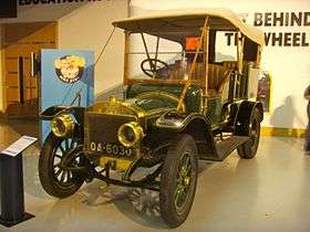 The oldest Austin, 1907 Heritage Motor Centre, Gaydon | |
| Overview | |
| Manufacturer | Austin |
| Production | 1906-1907 |
| Assembly | Longbridge plant, Birmingham, United Kingdom |
| Powertrain | |
| Engine | 4-cylinder 5,182cc T-head |
| Transmission | 4-speed gearbox |
| Chronology | |
| Successor | Austin 40 hp |
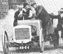
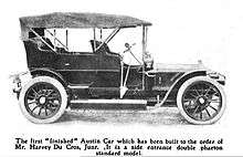
this photograph published 30 June 1906
In the last week of April 1906 a large body of motorists travelled to Longbridge "where snow lay full three inches deep on the ground and was still falling fast" to see the new Austin car, a conventional four-cylinder model with chain drive. The engine's tax rating would have been 32 hp. It was also available in a cheaper version as a 15/20 hp[note 1] complete at £500 (chassis, £425) as well as the 25/30 hp for £650 (chassis, £550). The sole concessionaire for sale of the cars was Mr Harvey du Cros junior[2] (1872-1928).
Between April and October 1906 only 23 cars, mostly 25-30s were sold. This was minute when compared with the output of the whole British motor industry. In the following 12 months to October 1907 147 cars of all models were sold.[3]
The 25-30 was manufactured for more than a year with a total of 65 cars produced.[4] It was replaced in 1907 by the Austin 40 hp which used a bored out (4¾ in x 5 in) and simplified 25-30 engine.[3]
Chassis
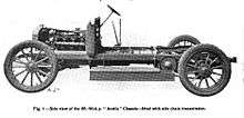
The frame was made of very stiff section steel. A subframe was provided to make the engine clutch and gearbox one unit. By the standards of its day the chassis was entirely orthodox but it was of first class quality and provided excellent reliability.[3]
 |
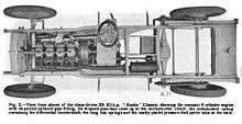 |
Engine
| Austin 25-30 | |
|---|---|
 | |
| Overview | |
| Manufacturer | Austin Motor Company |
| Layout | |
| Configuration | straight four |
| Displacement | 318 cu in (5,182 cc) |
| Cylinder bore | 4.5 in (115 mm) |
| Piston stroke | 5 in (127 mm) |
| Output | |
| Power output | 23 bhp (17 kW; 23 PS) @900 rpm Tax horsepower 32.8 |
| Chronology | |
| Successor | Austin 40 hp |
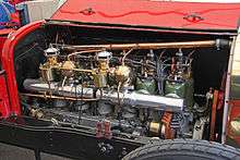
2 more cylinders, 1 more carburettor
Previous Herbert Austin cars for Wolseley Motors, which Austin founded, kept horizontal engines after vertical engines became the norm. Herbert Austin allowed his refusal to specify vertical engines to become the contract-breaking component of his disagreements with the Wolseley directors. He would provide a list of very pressing reasons for giving preference to horizontal engines. This 25-30, the first car bearing his own name, had a vertical engine. Either Austin reviewed his stance and changed it or his backers made him change.
This vertical straight 4-cylinder 318 cu in (5185 cc) T-head engine with 4½ in bore x 5 in stroke (114 mm x 127 mm)[1] was automatically governed to a maximum of 900 rpm.[3]
Cylinder block
Each cylinder is a separate casting.[1]
Fuel system
The carburettor is an automatic diaphragm Krebs type. The automatic throttle is coupled to the centrifugal governor which is mounted on the same shaft as the fan and can only be controlled by the accelerator pedal. The magneto is driven from the inlet valves' camshaft as is also the commutator and the pump for the engine lubrication system.[1]
Dual ignition
On the right hand side of the engine there is dual ignition at each cylinder first from the magneto supplying low-tension power to complex ignitors inside the inlet valve caps and again from conventional high-tension sparking plugs through a distributor from the accumulator (battery) dynamo and coil. The low tension igniter and the high tension sparking plug are mounted on the inspection cover above the inlet valves.[1]
A low tension make-and-break contact spindle rises diagonally from its camshaft through the main casting so it makes or breaks contact with the insulated contact pillar on the inlet valve cap. The necessary quick-break action comes from a coil spring at the bottom of the spindle. The high-tension sparking plugs are close alongside the contact pillars.[1]
Valve and ignition camshafts
The exhaust poppet valves are on the other side of the engine. Arranged symmetrically at the top of the engine the inlet and exhaust valves are interchangeable.[1]
The valves have a detachable cover over each valve giving easy access for adjusting seating or complete withdrawal. Between the cams and tappets there are fingers which can be set with the engine running. There is a similar arrangement for the ignition tappets. However the timing of the ignition can be varied with a lever above the steering wheel. The lever moves a timing shaft which moves the tappet pivot-pins inward or outward. The axis of the commutator shaft rocks at the same time.[1] This arrangement brought about oil sealing problems when pressure lubrication became more complicated.[3] The spur wheels that operate the two camshafts are enclosed in a neat dust-proof casing.[1]
Cooling
There is a centrifugal water pump mounted on the front left of the crankcase casting to draw cooled water from the bottom of the radiator. Independently formed jackets surround each cylinder to carry the cooling water. When cast the lower end of the jacket is completely open. A dome-shaped fitting is inserted at the top for hot water to return to the radiator and the bottom is closed by the exterior of the cylinder casting. This form of construction is to eliminate any chance of overheating from undetected air pockets.[1]
Crankcase
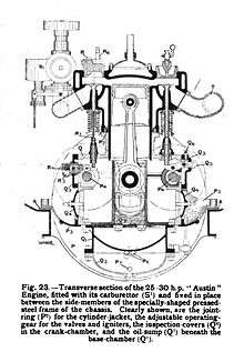
A rectangular cross-section aluminium casting holds the five main bearings and the bearings for the two camshafts. This makes the sump below the crankcase independent and its removal does not disturb the engine's crankshaft or its bearings. Either camshaft can be removed sideways at any time through large doors which also give access to the small rock-levers through which the cams operate the pushrods. Another set of detachable doors on each side gives access to each big end bearing. The aluminium casting forming the crankcase rests on two cast-steel cradles which firmly hold the engine in the chassis.[1]
Engine lubrication
Oil is drawn from the sump by the oil pump and delivered to the three inner main bearings and to the other bearings within the crank chamber. Oil is led into the centre of the crankpins by oil scoops which lubricate the big end bearings from inside. The end main bearings and each of the four cylinders receive measured doses of oil through a mechanical automatic lubricator. This lubricator, driven by chain, contains positive pumps to force the oil through each of six feed-pipes. Mounted on the dashboard the lubricator's sight glasses give visual confirmation oil is circulating.[1]
- Key to engine diagrams[note 2]
Transmission
The car was fitted with a four-speed gearbox and multiple disc clutch. In the first production car power was transmitted to the back wheels from the differential by chains though this system was noisy. A bevel-geared live rear axle was also available.[3]
| calendar
1906 |
calendar
1907 |
calendar
1908 | |
|---|---|---|---|
References
- The Austin Petrol Cars, Issue No 278, (No 18 Vol XI) 5 May 1906. The Automotor Journal, King & Co, Charing Cross, London.
- Automobile Notes. The Times, Tuesday, 1 May 1906; p. 6; Issue 38008
- R J Wyatt, The Austin 1905-1952, David & Charles, Newton Abbott, 1981 ISBN 0715379488
- Ian Dimmer, The Edwardian Austin, the survivors, The Vintage Austin Register Limited, 2014
Notes
- The 15-20 used the same engine as the 25-30 except that the cylinder bores were only 4 inches not 4½ inches. The following year with a slightly increased bore, 4⅛ in, the 15-20 was sold as Austin's 18-24
-
- Key to engine diagrams
- 1 dust proof cover for camshafts
- 2 special joint ring for the cylinder water jacket
- 3 cast steel cradles
- 4 camshaft
- 5 oil catchers / scoops for crankpins
- 6 return oil pipes to sump
- 7 oil supply pipe to oil pump
- 8 centrifugal water pump
- 1 base chamber
- 2 oil sump
- 3 castings carrying cam gear
- 4 inspection covers in crankcase by big ends
- 5 fulcrum pins for rock levers
- 6 adjustment screws to "time" exhaust valves
- 7 main bearing caps
- 1 insulated contact pillar
- 2 tappet rod igniters
- 3 low tension magneto AND timing shaft
- 4 adjustment screw
- 5 magneto
- 6 high tension ignition plugs
- 7 commutator
- 1 carburettor
- 1 asbestos packing rings
- 2 glands
- 3 baffles