Applications of UML
UML (Unified Modeling Language) is a modeling language used by software developers.[1] UML can be used to develop diagrams and provide users (programmers) with ready-to-use, expressive modeling examples.[note 1] Some UML tools generate program language code from UML.[2] UML can be used for modeling a system independent of a platform language. UML is a graphical language for visualizing, specifying, constructing, and documenting information about software-intensive systems.[3] UML gives a standard way to write a system model, covering conceptual ideas.[4][note 2] With an understanding of modeling, the use and application of UML can make the software development process more efficient.
| State Abstraction | |
|---|---|
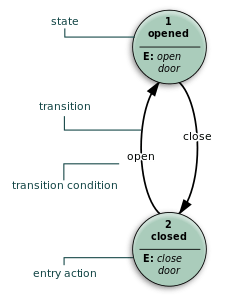
 This state diagram shows how UML can be used for designing a door system that can only be opened and closed | |
History
UML has applied to various activities since the second half of the 1990s and been used with object-oriented development methods.
Fields applying UML
UML has been used in following areas
|
|
|
UML can also be used to model nonsoftware systems, such as workflow in the legal systems, medical electronics and patient healthcare systems, and the design of hardware.[3]
| Diagram examples | |
|---|---|
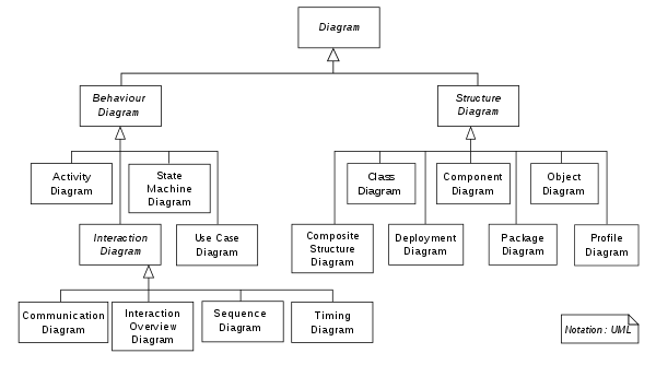
 Hierarchy of diagrams in UML 2.2
| |
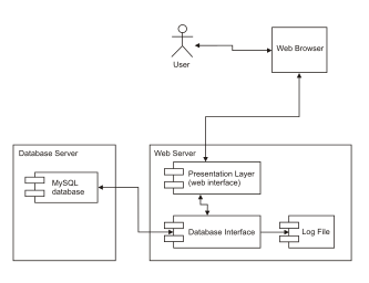
 UML deployment diagram showing a static view of a deployed system
This is an example of a deployed view of system in which user communicates to server through web browser | |
 Restaurant Use Case Diagram
In this example, the working of that restaurant is used to understand how UML can be used to implement a restaurant system. Here wait staff take order and serve food to patron. Then patron eat food, drink wine and pay bill. In this diagram patron, chef, cashier and wait staff are actors. | |
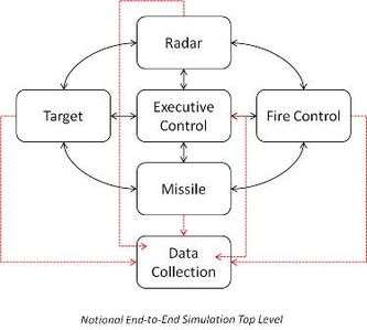
 Applications of UML in embedded systems | |
Modeling applications of UML using various diagrams
The following lists of UML diagrams and functionality summaries enable understanding of UML applications in real-world examples.
Structure diagrams and their applications
Structuring diagrams show a view of a system that shows the structure of the objects, including their classifiers, relationships, attributes and operations:
Behaviour diagrams and their applications
Behaviour diagrams are used to illustrate the behavior of a system, they are used extensively to describe the functionality of software systems. Some Behaviour diagrams are:
- Activity diagram
- State machine diagram
- Use Case Diagram[note 4]
Interaction diagrams and their applications
Interaction diagrams are subset of behaviour diagrams and emphasize the flow of control and data among the things in the system being modelled:
Web applications
Web applications of UML can be used to model user interfaces of web applications and make the purpose of the website clear. Web applications are software-intensive systems[5] and UML is among the efficient choice of languages for modeling them. Web software complexity of an application can be minimized using various UML tools.
UML-based web engineering aims at offering a UML profile that matches the needs of web development better. The following are examples:
- Representation of web applications using a set of models[5]
- Web app use case model
- Web app implementation model
- Web app deployment model
- Web app security model
- Web app site map
- To model pages, hyperlinks, and dynamic content on the client and server side.
- For modeling server side aspects of web page with one class and client side aspect with another and distinguishing the two by using UML's extension mechanism to define stereotype's and icons for each server and client page.
- Stereotypes in UML are used to define new semantics for modeling element.
- Forms in HTML can also be modeled using various UML constructs.
- UML can be used to express the execution of the system’s business logic in those Web-specific elements and technologies.
Embedded systems
Software in embedded systems design needs to be looked carefully for software specification and analysis. Unified Modeling Language and extension proposals in the realtime domain can be used for the development of new design flows. UML can be used for specification, design and implementation of modern embedded systems. UML can also be used for modelling the system from functional requirements through executable specifications and for that purpose it is important to be able to model the context for an embedded system – both environmental and user-driven.[6]
Some key concepts of UML related to embedded systems:
- UML is not a single language, but a set of notations, syntax and semantics to allow the creation of families of languages for particular applications.
- Extension mechanisms in UML like profiles, stereotypes, tags, and constraints can be used for particular applications.
- Use-case modelling to describe system environments, user scenarios, and test cases.
- UML has support for object-oriented system specification, design and modelling.
- Growing interest in UML from the embedded systems and realtime community.
- Support for state-machine semantics which can be used for modelling and synthesis.
- UML supports object-based structural decomposition and refinement.
A specific UML profile, called MARTE for Modeling and Analysis of Real-Time and Embedded systems, provides some extensions dedicated to the domain.
See also
References and notes
Notes
- UML can be applied in areas like embedded systems, web applications, commercial applications etc.
- For example, models of business processes and system functions, as well as things like classes written in a programming language, database schemas, and reusable software components.
- Such as, software engineering in aircraft combat systems
- Use Case Diagrams from UML are useful to understand real time systems
- Communication diagrams are used for showing communication between objects or parts.
- Sequence diagram are used for communication between objects in terms of sequences.
- Timing diagram are a specific type of interaction diagram where the focus is on timing constraints.
Citations
- "Power of UML related reference".
- "Some UML tools generate program language tools".
- "Grady Booch, Jacobson and rumbaugh book". Missing or empty
|url=(help) - [1412.2458] Systems, Views and Models of UML. By Ruth Breu Radu Grosu Franz Huber Bernhard Rumpe Wolfgang Schwerin. arXiv arxiv.org
- "Modeling Web Application Architectures with UML" (PDF).
- "UML for embedded systems". CiteSeerX 10.1.1.67.5101. Missing or empty
|url=(help)
External links
- http://www.uml.org/
- https://web.archive.org/web/20110906042707/http://www.itmweb.com/essay546.htm
- https://web.archive.org/web/20120331162632/http://oss.org.cn/ossdocs/development/rup/webapps.htm
- http://www.sereferences.com/uml-tools.php
- http://blogs.oracle.com/JavaFundamentals/entry/the_importance_of_using_unified